Curriculum
AP Physics C: Electricity AND Magnetism
8. Electric Charges, Fields, and Gauss’s Law
0/13
9. Electric Potential
0/7
10. Conductors and Capacitors
0/9
11. Electric Circuits
0/17
-
11. Electric Circuits
 Preview
-
11.1 Electric Current
Preview
-
11.1 Electric Current - Check yourself
 Preview
-
11.2 Simple Circuits
Preview
-
11.2 Simple Circuits - Check yourself
Preview
-
11.3 Resistance, Resistivity, and Ohm’s Law
Preview
-
11.3 Resistance, Resistivity, and Ohm’s Law - Check yourself
Preview
-
11.4 Electric Power
Preview
-
11.4 Electric Power - Check yourself
Preview
-
11.5 Compound Direct Current Circuits
Preview
-
11.5 Compound Direct Current Circuits - Check yourself
Preview
-
11.6 Kirchhoff’s Loop Rule
Preview
-
11.6 Kirchhoff’s Loop Rule - Check yourself
Preview
-
11.7 Kirchhoff’s Junction Rule
Preview
-
11.7 Kirchhoff’s Junction Rule - Check yourself
Preview
-
11.8 Resistor-Capacitor (RC) Circuits
Preview
-
11.8 Resistor-Capacitor (RC) Circuits - Check yourself
Preview
12. Magnetic Fields and Electromagnetism
0/9
13. Electromagnetic Induction
0/13
Text lesson
11.2 Simple Circuits
11.2 Simple Circuits — AP PHYSICS C: ELECTRICITY AND MAGNETISM notes: You will be able to describe the elements and electrical loops of a circuit, classify a circuit as closed, open or short, and read and draw schematic diagrams that use standard symbols and conventional current.
1
An electrical loop is a closed path through which charges may flow.
2
A battery or other source of potential difference provides the energy that moves the charges around the loop, and each element on the loop either stores energy, transfers it, or dissipates it.
3
A single circuit element may belong to more than one electrical loop.
4
When a circuit branches, an element that lies on a shared section of two loops is part of both of them, and the charges that pass through it may take either path at a branch point.
5
The loops are defined by the paths that charges can follow, and the drawing is only a representation of those paths.
An open circuit is one in which charges would not be able to flow, for example because a switch is off or a wire is broken.
In an open circuit the current in every element is zero, because there is no complete path for the charge.
A short circuit is one in which charges would be able to flow with no change in potential difference.
It is a path of negligible resistance connected across two points of a circuit, so the potential difference across the short is zero.
The current in a short is limited only by the source and by any other resistance in the loop, which can make it very large.
This is why short circuits heat wires and are dangerous.
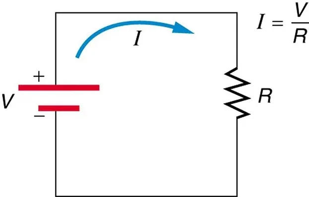
1
A circuit schematic is a diagram that uses standard symbols to show the elements of a circuit and how they are connected.
2
The behaviour of a circuit depends on the physical arrangement of its elements, so the schematic must show every connection exactly.
3
Wires that cross without a junction dot are not joined, and the two ends of an element are connected to different parts of the circuit.
4
The common symbols are as follows.
5
A battery is drawn as a series of long and short parallel lines, and the longer line marks the positive terminal.
6
A resistor is drawn as a zigzag.
7
A bulb is drawn as a circle with a cross inside.
8
A switch is drawn as a gap with a hinged arm.
9
A capacitor is drawn as two parallel plates, and an inductor as a coil.
10
An ammeter is a circle containing the letter A, and a voltmeter is a circle containing the letter V.
11
A variable element is shown by a diagonal arrow drawn through the standard symbol of that element.
12
Unless otherwise specified, all circuit schematics in this course are drawn using conventional current.
13
Conventional current leaves the positive terminal of a battery, flows through the external circuit, and returns to the negative terminal.
1
Moving a switch from one branch to another, or reconnecting a resistor from a series to a parallel position, changes which charges can flow and where they flow.
2
For this reason every analysis must start from the arrangement shown in the schematic, not from a list of the elements.
3
Topics 11.5 to 11.8 apply this principle to resistors and capacitors.
1
(a) The loop is broken at the switch, so charges cannot flow around it: the circuit is open
2
(b) The loop is complete and charges can flow through the bulb: the circuit is closed
3
(c) The wire provides a path between the battery terminals with no resistance, so there is no change in potential difference along that path.
4
The bulb is in parallel with the wire, so it has zero potential difference across it and carries no current.
Answer
(a) open; (b) closed; (c) short circuit across the battery, with the bulb bypassed.
1
The wire and the resistor are in parallel, so they have the same potential difference
2
The wire has negligible resistance, so the potential difference across it is zero, and therefore the potential difference across the resistor is also zero
3
Charge takes the wire and no current passes through the resistor even though its resistance is 4.0 Ω
Answer
The potential difference across both the wire and the resistor is 0 V, and the resistor carries no current
1
The diagonal arrow shows that the resistance of the element can be changed.
2
The elements are in one loop, so the current is the same in all of them, and by Ohm’s law (topic 11.3) the current in the loop is I = ΔV/R, where R is the total resistance.
3
A larger value of the variable resistance increases R, so the current decreases.
Answer
The arrow shows a variable resistance. A larger variable resistance reduces the current in the loop.
Calling every wire that connects two points a short circuit
A short requires a path across which there is no change in potential difference, usually a wire placed across a source or element.
Believing that a bulb glows when it is in a loop with an open switch
The open switch breaks the loop, so the current in the bulb is zero.
Reading the battery symbol backwards
The longer line marks the positive terminal.
Confusing the ammeter symbol (A) with the voltmeter symbol (V)
They measure different quantities and are connected differently.
Assuming that a circuit element belongs to only one loop
An element on a shared branch belongs to every loop that passes through it.
Avoid
Treating two crossing wires as joined when there is no junction dot at the crossing