Curriculum
EST II Physics
1. Mechanics
0/19
2. Electricity and Magnetism
0/15
-
2. Electricity and Magnetism
 Preview
-
2.1 Electric Charge and Coulomb’s Law
Preview
-
2.1 Electric Charge and Coulomb’s Law - Check yourself
 Preview
-
2.2 Electric Fields and Electric Potential
Preview
-
2.2 Electric Fields and Electric Potential - Check yourself
Preview
-
2.3 Capacitance
Preview
-
2.3 Capacitance - Check yourself
Preview
-
2.4 Current, Resistance and DC Circuits
Preview
-
2.4 Current, Resistance and DC Circuits - Check yourself
Preview
-
2.5 Electrical Energy and Power
Preview
-
2.5 Electrical Energy and Power - Check yourself
Preview
-
2.6 Magnetic Fields and Magnetic Forces
Preview
-
2.6 Magnetic Fields and Magnetic Forces - Check yourself
Preview
-
2.7 Electromagnetic Induction
Preview
-
2.7 Electromagnetic Induction - Check yourself
Preview
3. Waves and Optics
0/13
4. Heat and Thermodynamics
0/7
5. Modern Physics
0/11
6. Measurement, Analysis and Contemporary Physics
0/5
Text lesson
2.3 Capacitance
2.3 Capacitance — EST II PHYSICS notes: You will be able to define capacitance, calculate the capacitance of a parallel-plate capacitor with and without a dielectric, find the energy stored in a capacitor, combine capacitors in series and parallel, and find the time constant of a charging or discharging RC circuit.
The two conductors are called the plates.
When a capacitor is connected to a source of potential difference, one plate gains a charge +Q and the other plate gains an equal charge −Q.
The net charge on the capacitor is zero, but it stores charge Q on each plate.
The capacitance of a capacitor is the ratio of the charge on one plate to the potential difference between the plates: C = Q/ΔV.
Here C is the capacitance in farads (F), Q is the charge on each plate in coulombs (C), and ΔV is the potential difference in volts (V).
One farad equals one coulomb per volt.
Practical capacitors are usually measured in microfarads (μF), nanofarads (nF) or picofarads (pF).
The capacitance depends only on the geometry of the capacitor and the material between its plates, not on the charge or the voltage applied.
Doubling the voltage doubles the charge, and the ratio stays the same.
Its capacitance is C = ε0A/d, where ε0 = 8.85 × 10⁻¹² F/m is the permittivity of free space, A is the plate area in square metres (m2), and d is the separation in metres (m).
Increasing the plate area increases the capacitance, and increasing the separation decreases it.
Capacitance is directly proportional to area and inversely proportional to separation.
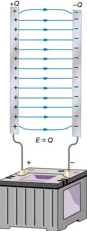
A dielectric is an insulating material placed between the plates.
The dielectric reduces the electric field between the plates for a given charge, so the potential difference for a given charge is reduced by the factor κ.
If the capacitor stays connected to the source, the potential difference stays the same, and the charge rises to κQ.
When a dielectric fills the space, the capacitance is increased by the dielectric constant κ, which is always greater than 1 for real materials: C = κε0A/d.
If a charged capacitor is disconnected from its source and then a dielectric is inserted, the charge stays the same, the potential difference falls to ΔV/κ, and the capacitance rises to κC.
The energy stored is the work needed to move the charge onto the capacitor.
It can be written as U = (1/2)QΔV, U = (1/2)CΔV2, or U = Q2/(2C).
Here U is in joules (J).
The three forms are equivalent, and the one to use depends on which quantities are given.
The energy stored is proportional to the square of the voltage.
Doubling the voltage across a given capacitor increases the energy stored by a factor of four.
1
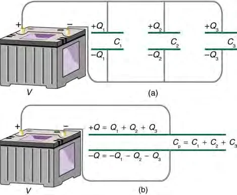
In a parallel combination, all capacitors have the same potential difference across them, and the total charge is shared between them.
2
The equivalent capacitance is the sum of the individual capacitances: Ceq = C1 + C2 + … .
3
Connecting capacitors in parallel is equivalent to increasing the plate area.
1
In a series combination, all capacitors carry the same charge, and the total potential difference is shared between them.
2
The reciprocal of the equivalent capacitance is the sum of the reciprocals: 1/Ceq = 1/C1 + 1/C2 + … .
3
The equivalent capacitance of a series combination is always smaller than the smallest individual capacitance.
4
Connecting capacitors in series is equivalent to increasing the plate separation.
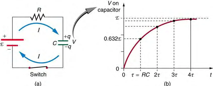
A capacitor in series with a resistor R and a source of emf forms an RC circuit.
The charge on the capacitor during charging is q = Q0(1 − e−t/τ), where Q0 = CV is the final charge, V is the emf of the source in volts, and the time constant is τ = RC.
When the switch is closed, the capacitor charges and its charge grows gradually rather than instantly.
The time constant τ is measured in seconds when R is in ohms and C is in farads.
After about five time constants the capacitor is more than 99% charged.
When a charged capacitor discharges through a resistor, the charge falls according to q = Q0e−t/τ.
The time constant has the same value τ = RC for charging and for discharging.
After one time constant, the capacitor has charged to 1 − e-1, or about 63%, of its final charge.
The current in the circuit falls from its initial value V/R to zero in the same pattern.
After one time constant the charge has fallen to about 37% of its initial value.
Example 1
Parallel-plate capacitor
1
C = ε0A/d = (8.85 × 10⁻¹² F/m)(0.010 m2)/(1.0 × 10−3 m) = 8.85 × 10⁻¹¹ F.
2
The charge is Q = CΔV = (8.85 × 10⁻¹¹ F)(12 V) = 1.06 × 10⁻⁹ C.
Answer
The capacitance is 8.9 × 10⁻¹¹ F (88 pF), and the charge on each plate is 1.1 × 10⁻⁹ C.
Example 2
Capacitors in series and in parallel
1
1/Ceq = 1/4.0 μF + 1/6.0 μF = (3 + 2)/(12 μF) = 5/12 μF−1, so Ceq = 2.4 μF.
2
The charge on each capacitor is the same Q = CeqΔV = (2.4 × 10⁻⁶ F)(12 V) = 2.9 × 10⁻⁵ C.
3
The potential difference across the 4.0 μF capacitor is Q/C1 = 2.9 × 10⁻⁵ C/4.0 × 10−6 F = 7.2 V.
4
Across the 6.0 μF capacitor it is 2.9 × 10⁻⁵ C/6.0 × 10−6 F = 4.8 V.
Answer
Ceq = 2.4 μF; each capacitor has a charge of 2.9 × 10⁻⁵ C; the voltages are 7.2 V and 4.8 V, which add to 12 V. If the same two capacitors were connected in parallel, the equivalent capacitance would be 10 μF.
Example 3
Energy stored in a capacitor
1
U = (1/2)CΔV2 = (1/2)(2.0 × 10−6 F)(100 V)2 = (1/2)(2.0 × 10−6)(1.0 × 10⁴) = 1.0 × 10⁻² J.
2
As a check, the charge is Q = (2.0 × 10⁻⁶ F)(100 V) = 2.0 × 10⁻⁴ C, and Q2/(2C) = (4.0 × 10⁻⁸)/(4.0 × 10−6) = 1.0 × 10⁻² J.
Answer
1.0 × 10⁻² J.
Example 4
Time constant of an RC circuit
1
τ = RC = (2.0 × 10⁶ Ω)(3.0 × 10⁻⁶ F) = 6.0 s.
2
What the symbols mean τ = time constant (s) · R = resistance (Ω) · C = capacitance (F); after one τ a discharging capacitor keeps 37% of its charge, The final charge is Q0 = (3.0 × 10⁻⁶ F)(9.0 V) = 2.7 × 10⁻⁵ C.
3
After one time constant, q = Q0(1 − e-1) = 0.63 × 2.7 × 10−5 C = 1.7 × 10⁻⁵ C.
Answer
The time constant is 6.0 s, and the charge after 6.0 s is about 1.7 × 10⁻⁵ C, which is 63% of the final charge.
Using the millimetre or micrometre value of the separation directly in C = ε0A/d
The separation must be converted to metres before the calculation.
Adding capacitances in series as if they were resistors in parallel
For capacitors in series, the reciprocals are added; for capacitors in parallel, the capacitances themselves are added.
Assuming that the charge on each capacitor in a series combination is the total charge
In series each capacitor carries the same charge, but the voltages divide between them. C = κε0A/d, so the capacitance is larger, not smaller.
Believing that the charge on a capacitor reaches its final value instantly
In an RC circuit the charge grows over several time constants.
Using the time constant in minutes or milliseconds without converting
With R in ohms and C in farads, τ is in seconds.