Curriculum
EST II Physics
1. Mechanics
0/19
2. Electricity and Magnetism
0/15
-
2. Electricity and Magnetism
 Preview
-
2.1 Electric Charge and Coulomb’s Law
Preview
-
2.1 Electric Charge and Coulomb’s Law - Check yourself
 Preview
-
2.2 Electric Fields and Electric Potential
Preview
-
2.2 Electric Fields and Electric Potential - Check yourself
Preview
-
2.3 Capacitance
Preview
-
2.3 Capacitance - Check yourself
Preview
-
2.4 Current, Resistance and DC Circuits
Preview
-
2.4 Current, Resistance and DC Circuits - Check yourself
Preview
-
2.5 Electrical Energy and Power
Preview
-
2.5 Electrical Energy and Power - Check yourself
Preview
-
2.6 Magnetic Fields and Magnetic Forces
Preview
-
2.6 Magnetic Fields and Magnetic Forces - Check yourself
Preview
-
2.7 Electromagnetic Induction
Preview
-
2.7 Electromagnetic Induction - Check yourself
Preview
3. Waves and Optics
0/13
4. Heat and Thermodynamics
0/7
5. Modern Physics
0/11
6. Measurement, Analysis and Contemporary Physics
0/5
Text lesson
2.4 Current, Resistance and DC Circuits
2.4 Current, Resistance and DC Circuits — EST II PHYSICS notes: You will be able to define electric current, use Ohm’s law and resistivity, find the equivalent resistance of series and parallel networks, explain how ammeters and voltmeters are connected, account for internal resistance and emf, and apply Kirchhoff’s junction and loop rules to a direct-current circuit.
1
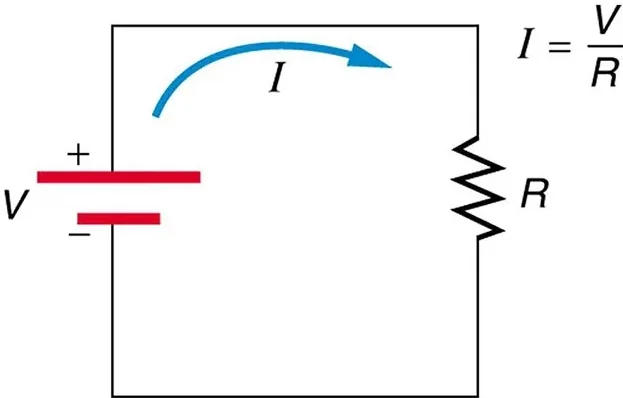
Electric current is the rate at which charge flows past a point in a circuit.
2
It is defined as I = ΔQ/Δt, where I is the current in amperes (A), ΔQ is the charge that passes the point in coulombs (C), and Δt is the time in seconds (s).
3
One ampere is one coulomb per second.
1
By convention, the direction of current is the direction in which positive charge would move.
2
In a metal wire the charges that actually move are electrons, which move in the opposite direction to the conventional current.
3
The electrons drift slowly, at speeds of millimetres per second, while the electric field that drives them travels through the wire at close to the speed of light.
4
In a steady DC circuit, the current is the same at every point along a single wire.
5
Charge is conserved, so charge cannot pile up or disappear at any point in the circuit.
The resistance of a conductor is the ratio of the potential difference across it to the current through it: R = ΔV/I.
A conductor with a large resistance allows only a small current for a given voltage.
Resistance is measured in ohms (Ω), where 1 Ω = 1 V/A.
Ohm’s law states that for an ohmic conductor, the current is proportional to the potential difference across it, so the resistance is constant.
Components whose resistance changes with current or voltage are nonohmic.
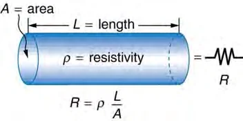
The resistance of a uniform wire depends on its material, length and cross-section: R = ρL/A.
A longer wire has greater resistance, and a wider wire has less resistance.
Metal wires at constant temperature are ohmic.
A filament lamp is nonohmic because its resistance increases as its temperature rises, so its current increases more slowly than the voltage.
Here ρ is the resistivity of the material in ohm metres (Ω·m), L is the length in metres (m), and A is the cross-sectional area in square metres (m2).
The potential difference across the network divides between the resistors.
The equivalent resistance is the sum of the individual resistances: Req = R1 + R2 + … .
The equivalent resistance of a series network is always larger than the largest individual resistance.
In a parallel network, the resistors are connected between the same two points, so each resistor has the same potential difference across it.
The current divides between the branches.
The reciprocals of the resistances add 1/Req = 1/R1 + 1/R2 + … .
The equivalent resistance of a parallel network is always smaller than the smallest individual resistance.
Two equal resistors R in parallel have an equivalent resistance of R/2.
A complex network can be simplified step by step find the equivalent resistance of each parallel group, then add the series resistances. Once the equivalent resistance and the source voltage are known, the total current is found from Ohm’s law.
To avoid changing the current in the circuit, an ideal ammeter has zero resistance.
Real ammeters have a very small resistance.
A voltmeter measures potential difference and is connected in parallel with the component across which the voltage is to be measured.
To avoid drawing current from the circuit, an ideal voltmeter has infinite resistance.
Real voltmeters have a very large resistance.
The emf (electromotive force) ε of a source is the energy supplied by the source to each coulomb of charge that passes through it.
The emf is the potential difference across the source when no current is drawn from it.
It is measured in volts.
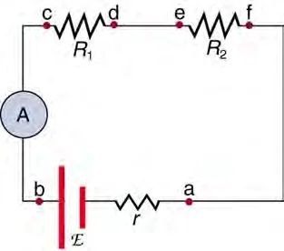
A real source has internal resistance r, which means that some energy is lost inside the source itself.
The terminal voltage is less than the emf whenever current flows.
When a current I is drawn, the terminal voltage, which is the potential difference between the terminals, is V = ε − Ir.
For a circuit with an external resistance R, the current is I = ε/(R + r).
It is a consequence of conservation of charge.
Kirchhoff’s loop rule states that the sum of the changes in potential around any closed loop in a circuit is zero.
It is a consequence of conservation of energy.
Going around a loop, a battery is a rise in potential of ε when it is traversed from its negative terminal to its positive terminal and a fall of ε in the opposite direction.
A resistor is a fall of IR when the loop is traversed in the direction of the current, and a rise of IR when it is traversed against the current.
To apply the rules, choose a current direction in each branch, label the currents, write one junction equation for each junction that gives new information, and write loop equations until there are enough equations to solve for the unknowns.
If an unknown current comes out negative, its true direction is opposite to the one chosen.
Example 1
Resistance from resistivity
1
R = ρL/A = (1.7 × 10⁻⁸ Ω·m)(2.0 m)/(1.0 × 10−6 m2) = 0.034 Ω.
2
The current is I = ΔV/R = 0.17 V/0.034 Ω = 5.0 A.
Answer
0.034 Ω, and a current of 5.0 A.
Example 2
Series and parallel network
1
For the parallel pair, 1/Rp = 1/6.0 + 1/3.0 = 1/6.0 + 2/6.0 = 3/6.0, so Rp = 2.0 Ω.
2
The series total is Req = 2.0 Ω + 4.0 Ω = 6.0 Ω.
3
The total current is I = 12 V/6.0 Ω = 2.0 A.
4
The potential difference across the parallel pair is 2.0 A × 2.0 Ω = 4.0 V, so the current in the 3.0 Ω resistor is 4.0 V/3.0 Ω = 1.33 A.
5
The current in the 6.0 Ω resistor is 4.0 V/6.0 Ω = 0.67 A, and 1.33 A + 0.67 A = 2.0 A.
Answer
Req = 6.0 Ω; the total current is 2.0 A; the current in the 3.0 Ω resistor is 1.3 A.
Example 3
Terminal voltage of a real battery
1
I = ε/(R + r) = 1.5 V/(2.5 Ω + 0.50 Ω) = 1.5 V/3.0 Ω = 0.50 A.
2
The terminal voltage is V = ε − Ir = 1.5 V − (0.50 A)(0.50 Ω) = 1.25 V.
3
As a check, IR = (0.50 A)(2.5 Ω) = 1.25 V
Answer
The current is 0.50 A and the terminal voltage is 1.25 V, which is less than the emf of 1.5 V
Example 4
Kirchhoff’s loop rule with two sources
1
Take the clockwise direction as positive.
2
Going clockwise around the loop, the 6.0 V source gives a rise of +6.0 V and the 2.0 V source gives a fall of −2.0 V.
3
The resistor gives a fall of −IR.
4
The loop rule gives 6.0 V − 2.0 V − I(2.0 Ω) = 0, so I = 4.0 V/2.0 Ω = 2.0 A.
Answer
2.0 A, flowing in the direction that the stronger 6.0 V source drives it, which is clockwise in this loop.
Adding resistances in parallel as if they were in series
Parallel resistances combine by their reciprocals, and the result is always smaller than the smallest branch.
Connecting an ammeter in parallel or a voltmeter in series
An ammeter must be in series with the component, and a voltmeter must be in parallel with it.
Taking the terminal voltage of a real battery to be its emf
When current flows, the terminal voltage is ε − Ir, which is smaller than ε.
Thinking that current is used up by a component
The current is the same before and after a resistor in series; the energy is what is used up, and it is transferred as heat.
Assuming that the direction of an electron’s motion is the direction of conventional current
Conventional current points opposite to the electron flow.
Avoid
Forgetting to convert resistivity and length into consistent units before using R = ρL/A, particularly when the area is given in cm2 or mm2