Curriculum
EST II Physics
1. Mechanics
0/19
2. Electricity and Magnetism
0/15
-
2. Electricity and Magnetism
 Preview
-
2.1 Electric Charge and Coulomb’s Law
Preview
-
2.1 Electric Charge and Coulomb’s Law - Check yourself
 Preview
-
2.2 Electric Fields and Electric Potential
Preview
-
2.2 Electric Fields and Electric Potential - Check yourself
Preview
-
2.3 Capacitance
Preview
-
2.3 Capacitance - Check yourself
Preview
-
2.4 Current, Resistance and DC Circuits
Preview
-
2.4 Current, Resistance and DC Circuits - Check yourself
Preview
-
2.5 Electrical Energy and Power
Preview
-
2.5 Electrical Energy and Power - Check yourself
Preview
-
2.6 Magnetic Fields and Magnetic Forces
Preview
-
2.6 Magnetic Fields and Magnetic Forces - Check yourself
Preview
-
2.7 Electromagnetic Induction
Preview
-
2.7 Electromagnetic Induction - Check yourself
Preview
3. Waves and Optics
0/13
4. Heat and Thermodynamics
0/7
5. Modern Physics
0/11
6. Measurement, Analysis and Contemporary Physics
0/5
Text lesson
2.7 Electromagnetic Induction
2.7 Electromagnetic Induction — EST II PHYSICS notes: You will be able to calculate magnetic flux, use Faraday’s law and Lenz’s law to find the size and direction of an induced emf, calculate the motional emf of a conductor moving in a magnetic field, and explain how generators, transformers and eddy currents work in outline.
For a flat surface of area A in a uniform field B, the flux is Φ = BA cosθ, where θ is the angle between the field and the normal to the surface.
(the line perpendicular), Flux is measured in webers (Wb), and 1 Wb = 1 T·m2.
The flux through a loop is greatest when the field is perpendicular to the plane of the loop, so that θ = 0°.
It is zero when the field lies in the plane of the loop, so that θ = 90°.
A flux change can be produced by changing the field strength, the area of the loop, or the angle between the loop and the field.
Faraday’s law states that the magnitude of the induced emf equals the number of turns N multiplied by the rate of change of flux: ε = −NΔΦ/Δt.
Here ε is the induced emf in volts (V), ΔΦ is the change in flux in webers (Wb), and Δt is the time taken in seconds (s).
A large flux change in a short time gives a large emf.
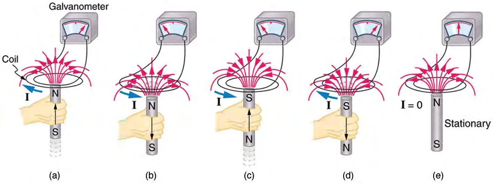
The emf depends on the rate of change of flux, not on the flux itself.
If the circuit is closed, the induced emf drives an induced current I = ε/R, where R is the total resistance of the circuit.
A coil in a strong steady field has no induced emf, because its flux does not change.
The induced current flows in the direction that creates a magnetic field opposing the change in flux that produces it.
The minus sign in Faraday’s law expresses this opposition.
When the north pole of a magnet is pushed into a coil, the flux through the coil increases.
The induced current produces a field that opposes this increase, so the face of the coil nearest the magnet becomes a north pole and repels the magnet.
When the magnet is pulled out, the flux decreases, and the induced current reverses so that the face nearest the magnet becomes a south pole and attracts it back.
Lenz’s law is a consequence of conservation of energy work has to be done to push a magnet into a coil, and this work is what becomes electrical energy.
This is called the motional emf, and it is given by ε = BLv.
The emf is the same as the emf given by Faraday’s law for the area swept out by the conductor per second.
If the moving conductor is part of a closed circuit of resistance R, the induced current is I = BLv/R.
This current carries charge in the conductor, so the field exerts a force F = BIL on the conductor.
By Lenz’s law this force opposes the motion, so work must be done to keep the conductor moving at constant speed.
The power needed for this is equal to the electrical power produced, εI.
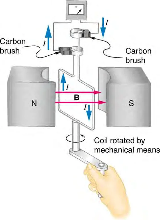
In a simple AC generator, a coil of N turns and area A rotates at a constant angular speed ω in a uniform magnetic field B.
The flux through the coil changes sinusoidally, so the induced emf is also sinusoidal: ε = NBAω sinωt.
The maximum emf is εmax = NBAω, and it increases with the number of turns, the field, the area and the rotation speed.
A transformer uses a changing current in one coil to induce an emf in another coil.
For an ideal transformer, the voltages are in the ratio of the number of turns: Vs/Vp = Ns/Np.
For an ideal transformer, the power input equals the power output, so VpIp = VsIs.
A transformer works only with a changing current, because a steady current produces no changing flux and induces no emf in the secondary coil.
The primary coil with Np turns is connected to an AC supply, and the secondary coil with Ns turns is linked to it through a shared iron core.
A step-up transformer has more turns on the secondary, and a step-down transformer has fewer.
A step-up transformer therefore gives a smaller current on the secondary side than on the primary side.
Eddy currents are induced circulating currents that flow in a bulk conductor when it moves through a magnetic field or is placed in a changing field.
Their direction, by Lenz’s law, opposes the change that produces them.
Eddy currents heat the conductor, and they produce a force that opposes the motion of the conductor.
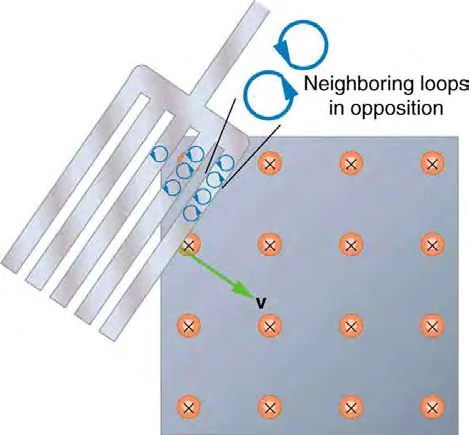
Eddy currents are used in magnetic braking, for example in some trains and in the brakes of heavy vehicles, where the braking force is produced without contact.
They are also used in metal detectors.
In transformers, the iron core is made of thin insulated sheets called laminations, which reduce the size of eddy currents and so reduce energy losses as heat.
Example 1
Magnetic flux through a tilted loop
1
Φ = BA cosθ = (0.50 T)(0.020 m2) cos 60° = (0.010 T·m2)(0.5) = 5.0 × 10⁻³ Wb.
Answer
5.0 × 10⁻³ Wb.
Example 2
Induced emf and current in a coil
1
|ε| = N|ΔΦ|/Δt = (100)(2.0 × 10⁻³ Wb)/(0.50 s) = 0.40 V.
2
The current is I = ε/R = 0.40 V/4.0 Ω = 0.10 A.
Answer
The induced emf is 0.40 V and the induced current is 0.10 A.
Example 3
Motional emf of a sliding rod
1
ε = BLv = (0.20 T)(0.50 m)(4.0 m/s) = 0.40 V.
2
The current is I = ε/R = 0.40 V/2.0 Ω = 0.20 A.
3
The opposing force is F = BIL = (0.20 T)(0.20 A)(0.50 m) = 0.020 N.
4
The power needed is P = Fv = (0.020 N)(4.0 m/s) = 0.080 W, which equals εI = (0.40 V)(0.20 A) = 0.080 W.
Answer
0.40 V; 0.20 A; a force of 0.020 N opposing the motion; and a power of 0.080 W.
Example 4
Ideal step-down transformer
1
Vs = Vp(Ns/Np) = (120 V)(60/1200) = 6.0 V.
2
The power output is VsIs = (6.0 V)(3.0 A) = 18 W.
3
For an ideal transformer, the primary current is Ip = 18 W/120 V = 0.15 A.
Answer
The secondary voltage is 6.0 V and the primary current is 0.15 A.
Thinking that a large flux produces a large emf
Faraday’s law depends on the rate of change of flux, so a constant flux induces no emf.
Forgetting the angle in the flux formula
The flux is BA cosθ, where θ is measured from the normal to the surface, not from the surface itself.
Reversing the direction of the induced current
Lenz’s law says the induced current opposes the change, so it reverses when the change reverses.
Using the turns ratio the wrong way round in a transformer
The voltage ratio is Vs/Vp = Ns/Np, and the current ratio is the inverse.
Expecting a transformer to work with a steady DC supply
Only a changing current produces a changing flux and an induced emf in the secondary.
Using ε = BLv when the velocity is not perpendicular to the field or to the conductor
Only the perpendicular components contribute.