Curriculum
AP PHYSICS 2
9. Thermodynamics
0/13
10. Electric Force, Field, and Potential
0/15
11. Electric Circuits
0/17
-
11. Electric Circuits
 Preview
-
11.1 Electric Current
Preview
-
11.1 Electric Current - Check yourself
 Preview
-
11.2 Simple Circuits
Preview
-
11.2 Simple Circuits - Check yourself
Preview
-
11.3 Resistance, Resistivity, and Ohm’s Law
Preview
-
11.3 Resistance, Resistivity, and Ohm’s Law - Check yourself
Preview
-
11.4 Electric Power
Preview
-
11.4 Electric Power - Check yourself
Preview
-
11.5 Compound Direct Current (DC) Circuits
Preview
-
11.5 Compound Direct Current (DC) Circuits - Check yourself
Preview
-
11.6 Kirchhoff’s Loop Rule
Preview
-
11.6 Kirchhoff’s Loop Rule - Check yourself
Preview
-
11.7 Kirchhoff’s Junction Rule
Preview
-
11.7 Kirchhoff’s Junction Rule - Check yourself
Preview
-
11.8 Resistor-Capacitor (RC) Circuits
Preview
-
11.8 Resistor-Capacitor (RC) Circuits - Check yourself
Preview
12. Magnetism and Electromagnetism
0/9
13. Geometric Optics
0/9
14. Waves, Sound, and Physical Optics
0/19
15. Modern Physics
0/17
Text lesson
11.5 Compound Direct Current (DC) Circuits
11.5 Compound Direct Current (DC) Circuits — AP PHYSICS 2: ALGEBRA-BASED notes: You will be able to find the equivalent resistance of resistors connected in series and in parallel, analyse a circuit with a battery of internal resistance, and explain how ideal and nonideal ammeters and voltmeters are connected and how they affect measurements.
In a series connection, any charge that passes through one element must pass through every other element in the same connection, because there is no other path available.
The current is therefore the same in every element of a series connection.
In a parallel connection, charge can flow through one of two or more paths.
Each path connects the same two points of the circuit, so the potential difference across every branch of a parallel connection is the same.
The current divides between the branches, and more current flows in the branch with lower resistance.
A circuit with several resistors can be analysed as though it were a single resistor with an equivalent resistance Req.
Replacing a group of resistors by its equivalent resistance does not change the current drawn from the battery or the potential difference across the group, so it is a valid way to simplify the circuit before applying Ohm’s law.
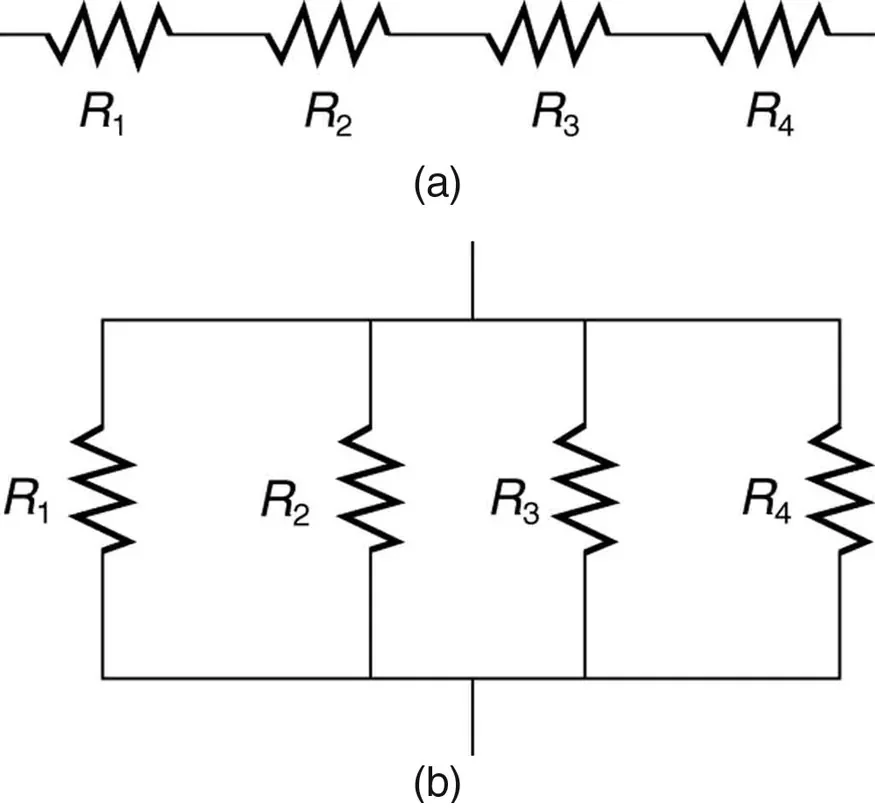
Adding resistors in series always increases the total resistance, because each extra element adds an obstacle that every charge must pass through.
For a series combination, the potential difference across the group is shared among the resistors.
Series
Each resistor has a potential difference V = IR across it, where I is the common current in amperes (A).
A larger resistance in the series chain takes a larger share of the total potential difference.

Adding a resistor in parallel always reduces the equivalent resistance of the group.
A parallel connection gives the charges more paths to travel, so the group as a whole conducts better than any single branch.
The equivalent resistance of two resistors in parallel can be written as Req = R1R2/(R1 + R2), and it is always smaller than the smaller of the two resistances.
1
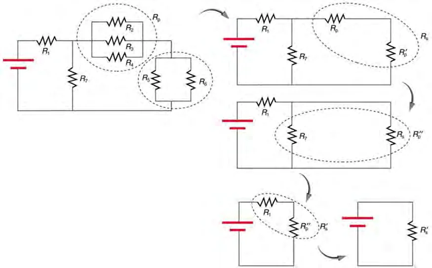
To analyse a compound circuit, first identify which resistors are in series and which are in parallel.
2
Replace each parallel group by its equivalent resistance, then add the series resistances.
3
Once the circuit has been reduced to a single equivalent resistor, the total current from the battery follows from Ohm’s law, I = ε/Req, where ε is the emf of the battery in volts (V) and I is the current in amperes (A).
4
Then work back through the circuit.
5
The current through a series element equals the total current, and the potential difference across a parallel group equals the potential difference across the battery that it is connected to.
6
The current in each parallel branch is found from Ibranch = ΔV/Rbranch, and the branch currents add up to the total current.
The emf is the potential difference the battery would supply if it were ideal, and it is the potential difference measured across its terminals when there is no current in the battery.
Ideal wires also have negligible resistance.
The resistance of a good conductor may normally be neglected, because it is much smaller than the resistance of the other elements of the circuit.
This simplification is only valid if the circuit contains other elements that do have resistance.
A real battery is modelled as an ideal battery with emf ε in series with a resistor of resistance r, called its internal resistance, which is measured in ohms (Ω).
When there is a current I in the battery, the potential difference across its terminals is reduced below the emf.
The terminal potential difference is ΔVterminal = ε − Ir, where ΔVterminal is in volts (V), I is in amperes (A), and r is in ohms (Ω).
The drop Ir is the potential difference lost inside the battery itself.
For a battery with internal resistance connected to an external resistance R, the internal and external resistances are in series.
The current is therefore I = ε/(R + r).
A battery delivers the most current to a circuit when its external resistance is small, and the terminal potential difference falls as the current rises.
A battery with a large internal resistance is a poor source of potential difference when it supplies a large current.
It must be connected in series with that element, so that all of the current being measured passes through the meter.
An ideal ammeter has zero resistance, so it does not change the current in the branch it is connected to.
A voltmeter measures the electric potential difference between two points in a circuit.
It must be connected in parallel with the element across which the potential difference is being measured.
An ideal voltmeter has infinite resistance, so no charge flows through it and it does not change the current in the circuit.
Meters
Real meters are nonideal, and they change the circuit they measure.
A real ammeter has a small but nonzero resistance, which adds to the total resistance in its branch and lowers the current.
A real voltmeter draws a small current, which lowers the potential difference across the element it is connected to.
In AP Physics 2, these effects are described qualitatively.
Unless stated otherwise, all batteries, wires and meters in a problem are assumed to be ideal.
Question
Three resistors of 4.0 Ω, 6.0 Ω and 10.0 Ω are connected in series with an ideal 12 V battery. Find the equivalent resistance, the current in the battery, and the potential difference across the 4.0 Ω resistor.
1
Req = 4.0 Ω + 6.0 Ω + 10.0 Ω = 20.0 Ω.
2
The current is I = ε/Req = 12 V/20.0 Ω = 0.600 A.
3
The potential difference across the 4.0 Ω resistor is ΔV = IR = (0.600 A)(4.0 Ω) = 2.4 V.
Answer
The equivalent resistance is 20.0 Ω, the current is 0.60 A, and the potential difference across the 4.0 Ω resistor is 2.4 V.
Question
A 4.0 Ω resistor is connected in series with a parallel pair of resistors of 6.0 Ω and 3.0 Ω. The combination is connected to an ideal 12 V battery. Find the equivalent resistance of the parallel pair, the total current, the current in the 3.0 Ω resistor, and the current in the 6.0 Ω resistor.
1
For the parallel pair, 1/Rp = 1/6.0 Ω + 1/3.0 Ω = 1/6.0 + 2/6.0 = 3/6.0 Ω−1, so Rp = 2.0 Ω.
2
The total resistance is Req = 4.0 Ω + 2.0 Ω = 6.0 Ω.
3
The total current is I = 12 V/6.0 Ω = 2.0 A.
4
The parallel pair has the full 2.0 A flowing into it, so its potential difference is ΔVp = (2.0 A)(2.0 Ω) = 4.0 V.
5
The current in the 6.0 Ω branch is 4.0 V/6.0 Ω = 0.67 A, and the current in the 3.0 Ω branch is 4.0 V/3.0 Ω = 1.33 A.
6
As a check, 0.67 A + 1.33 A = 2.0 A.
Answer
The parallel pair has an equivalent resistance of 2.0 Ω, the total current is 2.0 A, the current in the 3.0 Ω resistor is 1.3 A, and the current in the 6.0 Ω resistor is 0.67 A.
Question
A battery of emf 12.0 V and internal resistance 0.50 Ω is connected to an external resistor of 5.5 Ω. Find the current in the battery and the terminal potential difference across its terminals.
1
The internal and external resistances are in series, so the total resistance is 5.5 Ω + 0.50 Ω = 6.0 Ω.
2
The current is I = ε/(R + r) = 12.0 V/6.0 Ω = 2.0 A.
3
The terminal potential difference is ΔVterminal = ε − Ir = 12.0 V − (2.0 A)(0.50 Ω) = 12.0 V − 1.0 V = 11.0 V.
4
As a check, the potential difference across the external resistor is (2.0 A)(5.5 Ω) = 11.0 V.
Answer
The current is 2.0 A and the terminal potential difference is 11.0 V. The 1.0 V lost inside the battery is the drop Ir.
Adding resistors in parallel as though they were in series.
Series resistances add directly, but for parallel resistors the inverses add, and the equivalent resistance is smaller than the smallest branch.
Using the total current as the current in every branch of a parallel group.
The branch currents add to the total, and each branch current depends on its own resistance.
Forgetting the internal resistance of a battery when the current in it is not zero.
The terminal potential difference is ε − Ir, not ε.
Connecting an ammeter in parallel with an element, or a voltmeter in series.
An ammeter must be in series, and a voltmeter must be in parallel.
Assuming that a wire always has negligible resistance.
Wires are treated as ideal only when the circuit contains other elements that do have resistance.
Avoid
Confusing the emf of a battery with its terminal potential difference when the battery is supplying current.