Curriculum
AP PHYSICS 2
9. Thermodynamics
0/13
10. Electric Force, Field, and Potential
0/15
11. Electric Circuits
0/17
-
11. Electric Circuits
 Preview
-
11.1 Electric Current
Preview
-
11.1 Electric Current - Check yourself
 Preview
-
11.2 Simple Circuits
Preview
-
11.2 Simple Circuits - Check yourself
Preview
-
11.3 Resistance, Resistivity, and Ohm’s Law
Preview
-
11.3 Resistance, Resistivity, and Ohm’s Law - Check yourself
Preview
-
11.4 Electric Power
Preview
-
11.4 Electric Power - Check yourself
Preview
-
11.5 Compound Direct Current (DC) Circuits
Preview
-
11.5 Compound Direct Current (DC) Circuits - Check yourself
Preview
-
11.6 Kirchhoff’s Loop Rule
Preview
-
11.6 Kirchhoff’s Loop Rule - Check yourself
Preview
-
11.7 Kirchhoff’s Junction Rule
Preview
-
11.7 Kirchhoff’s Junction Rule - Check yourself
Preview
-
11.8 Resistor-Capacitor (RC) Circuits
Preview
-
11.8 Resistor-Capacitor (RC) Circuits - Check yourself
Preview
12. Magnetism and Electromagnetism
0/9
13. Geometric Optics
0/9
14. Waves, Sound, and Physical Optics
0/19
15. Modern Physics
0/17
Text lesson
11.8 Resistor-Capacitor (RC) Circuits
11.8 Resistor-Capacitor (RC) Circuits — AP PHYSICS 2: ALGEBRA-BASED notes: You will be able to find the equivalent capacitance of capacitors in series and in parallel, and describe qualitatively how the potential difference, charge, current and stored energy change as a resistor-capacitor circuit charges and discharges.
1Equivalent capacitance of capacitors in series2Equivalent capacitance of capacitors in series3Equivalent capacitance of capacitors in series4Equivalent capacitance of capacitors in series5Equivalent capacitance of capacitors in series6Equivalent capacitance of capacitors in series
1Equivalent capacitance of capacitors in parallel2Equivalent capacitance of capacitors in parallel3Equivalent capacitance of capacitors in parallel
1Charging an RC circuit2Charging an RC circuit3Charging an RC circuit4Charging an RC circuit5Charging an RC circuit6Charging an RC circuit7Charging an RC circuit8Charging an RC circuit9Charging an RC circuit
Charging an RC circuit
Charging an RC circuit
An RC circuit is a circuit containing a resistor of resistance R in ohms (Ω) and a capacitor in series with a battery of emf ε.
1 / 9Next ▶
Charging an RC circuit
1
When the circuit is closed, the capacitor begins to charge.
2
The time constant of the circuit is
3
τ
4
=
5
RC
6
, measured in seconds (s) when
◀ Previous2 / 9Next ▶
Charging an RC circuit
1
R
2
is in ohms and
3
C
4
is in farads.
5
The time constant is a measure of how quickly the capacitor charges or discharges.
6
At the instant the circuit is closed, the uncharged capacitor acts like a wire
because charge can flow easily to and from its plates.
◀ Previous3 / 9Next ▶
Charging an RC circuit
Charging an RC circuit
The potential difference across the capacitor is then zero, and the full emf appears across the resistor.
The current at this instant is
I
0
ε
/
◀ Previous4 / 9Next ▶
Charging an RC circuit
1
which is the largest current in the circuit.
2
As the capacitor charges, its charge and potential difference increase, and the current in the branch decreases.
3
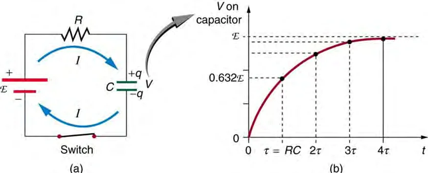
In one time constant, the charge on the capacitor rises to about 63 percent of its final value.
4
Each further time constant closes a large part of the remaining gap
so the charge approaches its final value asymptotically.
5
These are qualitative descriptions: the graph of charge against time rises steeply at first and then levels off,
6
and the graph of current falls steeply at first and then approaches zero.
◀ Previous5 / 9Next ▶
Charging an RC circuit
Charging an RC circuit
After a long time, the capacitor is fully charged.
Its potential difference equals the emf, Δ
V
, and the current in its branch is zero
because no charge flows once the capacitor is fully charged.
The final charge is
Q
◀ Previous6 / 9Next ▶
Charging an RC circuit
Charging an RC circuit
final
.
The energy stored in the capacitor is
U
= ½
(Δ
◀ Previous7 / 9Next ▶
Charging an RC circuit
1
)
2
2
3
in joules (J),
4
which increases as the capacitor charges and reaches its maximum value in the steady state.
◀ Previous8 / 9Next ▶
Charging a capacitor: the differential equation: Charging an RC circuit: capacitor voltage rises exponentially toward the emf, reaching 63.2% after one time constant.
Charging an RC circuit
◀ Previous9 / 9
1Discharging an RC circuit and steady states2Discharging an RC circuit and steady states3Discharging an RC circuit and steady states
Discharging an RC circuit and steady states
Discharging an RC circuit and steady states
If a charged capacitor is connected in a circuit with a resistor and no battery, it discharges through the resistor.
1 / 3Next ▶
Discharging an RC circuit and steady states
1
Immediately after the discharge begins, the charge on its plates and the energy stored in it begin to decrease,
2
and the current in the branch is at its largest.
3
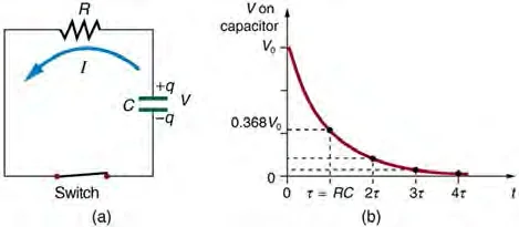
After one time constant, the charge has fallen to about 37 percent of its initial value.
4
As the capacitor discharges, its charge, its potential difference and the current in its branch all decrease until a steady state is reached. In the final steady state the capacitor has no charge, no potential difference across it and no current in the branch.
5
The boundary of the course is qualitative: students describe the initial and final states of an RC circuit mathematically
but do not model the time dependence of charge or current.
6
After charging or discharging for times much greater than the time constant, the capacitor and its branch may be treated as being in steady state.
◀ Previous2 / 3Next ▶
Discharging a capacitor: Discharging an RC circuit: capacitor voltage decays exponentially, falling to 36.8% of V0 after one time constant.
Discharging an RC circuit and steady states
 ⤢ Enlarge
Discharging an RC circuit and steady states
In practice, several time constants is taken as the point at which the change is essentially complete.
◀ Previous3 / 3
1Example 1: Equivalent capacitance of series and parallel cap2Worked examples3Worked examples4Worked examples5Worked examples6Example 3: Initial and final states of a charging RC circuit7Example 3: Initial and final states of a charging RC circuit8Example 3: Initial and final states of a charging RC circuit9Example 3: Initial and final states of a charging RC circuit10Example 3: Initial and final states of a charging RC circuit
Key terms
| Term | Meaning |
|---|---|
| Capacitance (C) | The ratio of the charge on one plate to the potential difference across a capacitor, measured in farads (F). |
| Equivalent capacitance (Ceq) | The single capacitance that can replace a set of capacitors in a circuit without changing its behaviour. |
| Series connection | A connection in which charge passing through one element must pass through all the others, so each capacitor has the same charge. |
| Parallel connection | A connection in which each element is connected across the same two points, so each has the same potential difference. |
| RC circuit | A circuit containing a resistor and a capacitor, whose charge and current change over time. |
| Time constant (τ) | The product RC of the resistance and capacitance of an RC circuit, measured in seconds, which measures how quickly the capacitor charges or discharges. |
| Charging | The process in which charge builds up on the plates of a capacitor connected to a source of emf. |
| Discharging | The process in which the charge on a charged capacitor decreases as it drives current through a circuit. |
| Steady state | The condition reached after a long time, in which the potential difference and current in a branch no longer change. |
1Avoid these mistakes2Avoid these mistakes3Avoid these mistakes