Curriculum
College Physics for AP Courses 2e
Unit 1: Introduction: The Nature of Science and Physics
0/10
-
Unit 1 overview: Introduction: The Nature of Science and Physics
 Text lessonPreview
-
1.1 Physics: An Introduction
Text lessonPreview
-
1.1 Physics: An Introduction - Check yourself
 6 questionsPreview
-
1.2 Physical Quantities and Units
Text lessonPreview
-
1.2 Physical Quantities and Units - Check yourself
6 questionsPreview
-
1.3 Accuracy, Precision, and Significant Figures
Text lessonPreview
-
1.3 Accuracy, Precision, and Significant Figures - Check yourself
6 questionsPreview
-
1.4 Approximation
Text lessonPreview
-
1.4 Approximation - Check yourself
6 questionsPreview
-
Unit 1 review quiz: Introduction: The Nature of Science and Physics
10 questionsPreview
Unit 2: Kinematics
0/18
-
Unit 2 overview: Kinematics
Text lessonPreview
-
2.1 Displacement
Text lessonPreview
-
2.1 Displacement - Check yourself
6 questionsPreview
-
2.2 Vectors, Scalars, and Coordinate Systems
Text lessonPreview
-
2.2 Vectors, Scalars, and Coordinate Systems - Check yourself
6 questionsPreview
-
2.3 Time, Velocity, and Speed
Text lessonPreview
-
2.3 Time, Velocity, and Speed - Check yourself
6 questionsPreview
-
2.4 Acceleration
Text lessonPreview
-
2.4 Acceleration - Check yourself
6 questionsPreview
-
2.5 Motion Equations for Constant Acceleration in One Dimension
Text lessonPreview
-
2.5 Motion Equations for Constant Acceleration in One Dimension - Check yourself
6 questionsPreview
-
2.6 Problem-Solving Basics for One-Dimensional Kinematics
Text lessonPreview
-
2.6 Problem-Solving Basics for One-Dimensional Kinematics - Check yourself
6 questionsPreview
-
2.7 Falling Objects
Text lessonPreview
-
2.7 Falling Objects - Check yourself
6 questionsPreview
-
2.8 Graphical Analysis of One-Dimensional Motion
Text lessonPreview
-
2.8 Graphical Analysis of One-Dimensional Motion - Check yourself
6 questionsPreview
-
Unit 2 review quiz: Kinematics
10 questionsPreview
Unit 3: Two-Dimensional Kinematics
0/12
-
Unit 3 overview: Two-Dimensional Kinematics
Text lessonPreview
-
3.1 Kinematics in Two Dimensions: An Introduction
Text lessonPreview
-
3.1 Kinematics in Two Dimensions: An Introduction - Check yourself
6 questionsPreview
-
3.2 Vector Addition and Subtraction: Graphical Methods
Text lessonPreview
-
3.2 Vector Addition and Subtraction: Graphical Methods - Check yourself
6 questionsPreview
-
3.3 Vector Addition and Subtraction: Analytical Methods
Text lessonPreview
-
3.3 Vector Addition and Subtraction: Analytical Methods - Check yourself
6 questionsPreview
-
3.4 Projectile Motion
Text lessonPreview
-
3.4 Projectile Motion - Check yourself
6 questionsPreview
-
3.5 Addition of Velocities
Text lessonPreview
-
3.5 Addition of Velocities - Check yourself
6 questionsPreview
-
Unit 3 review quiz: Two-Dimensional Kinematics
10 questionsPreview
Unit 4: Dynamics: Force and Newton's Laws of Motion
0/18
-
Unit 4 overview: Dynamics: Force and Newton's Laws of Motion
Text lessonPreview
-
4.1 Development of Force Concept
Text lessonPreview
-
4.1 Development of Force Concept - Check yourself
6 questionsPreview
-
4.2 Newton’s First Law of Motion: Inertia
Text lessonPreview
-
4.2 Newton’s First Law of Motion: Inertia - Check yourself
6 questionsPreview
-
4.3 Newton’s Second Law of Motion: Concept of a System
Text lessonPreview
-
4.3 Newton’s Second Law of Motion: Concept of a System - Check yourself
6 questionsPreview
-
4.4 Newton’s Third Law of Motion: Symmetry in Forces
Text lessonPreview
-
4.4 Newton’s Third Law of Motion: Symmetry in Forces - Check yourself
6 questionsPreview
-
4.5 Normal, Tension, and Other Examples of Forces
Text lessonPreview
-
4.5 Normal, Tension, and Other Examples of Forces - Check yourself
6 questionsPreview
-
4.6 Problem-Solving Strategies
Text lessonPreview
-
4.6 Problem-Solving Strategies - Check yourself
6 questionsPreview
-
4.7 Further Applications of Newton’s Laws of Motion
Text lessonPreview
-
4.7 Further Applications of Newton’s Laws of Motion - Check yourself
6 questionsPreview
-
4.8 Extended Topic: The Four Basic Forces—An Introduction
Text lessonPreview
-
4.8 Extended Topic: The Four Basic Forces—An Introduction - Check yourself
6 questionsPreview
-
Unit 4 review quiz: Dynamics: Force and Newton's Laws of Motion
10 questionsPreview
Unit 5: Further Applications of Newton's Laws: Friction, Drag, and Elasticity
0/8
-
Unit 5 overview: Further Applications of Newton's Laws: Friction, Drag, and Elasticity
Text lessonPreview
-
5.1 Friction
Text lessonPreview
-
5.1 Friction - Check yourself
6 questionsPreview
-
5.2 Drag Forces
Text lessonPreview
-
5.2 Drag Forces - Check yourself
6 questionsPreview
-
5.3 Elasticity: Stress and Strain
Text lessonPreview
-
5.3 Elasticity: Stress and Strain - Check yourself
6 questionsPreview
-
Unit 5 review quiz: Further Applications of Newton's Laws: Friction, Drag, and Elasticity
10 questionsPreview
Unit 6: Uniform Circular Motion and Gravitation
0/14
-
Unit 6 overview: Uniform Circular Motion and Gravitation
Text lessonPreview
-
6.1 Rotation Angle and Angular Velocity
Text lessonPreview
-
6.1 Rotation Angle and Angular Velocity - Check yourself
6 questionsPreview
-
6.2 Centripetal Acceleration
Text lessonPreview
-
6.2 Centripetal Acceleration - Check yourself
6 questionsPreview
-
6.3 Centripetal Force
Text lessonPreview
-
6.3 Centripetal Force - Check yourself
6 questionsPreview
-
6.4 Fictitious Forces and Non-inertial Frames: The Coriolis Force
Text lessonPreview
-
6.4 Fictitious Forces and Non-inertial Frames: The Coriolis Force - Check yourself
6 questionsPreview
-
6.5 Newton’s Universal Law of Gravitation
Text lessonPreview
-
6.5 Newton’s Universal Law of Gravitation - Check yourself
6 questionsPreview
-
6.6 Satellites and Kepler’s Laws: An Argument for Simplicity
Text lessonPreview
-
6.6 Satellites and Kepler’s Laws: An Argument for Simplicity - Check yourself
6 questionsPreview
-
Unit 6 review quiz: Uniform Circular Motion and Gravitation
10 questionsPreview
Unit 7: Work, Energy, and Energy Resources
0/20
-
Unit 7 overview: Work, Energy, and Energy Resources
Text lessonPreview
-
7.1 Work: The Scientific Definition
Text lessonPreview
-
7.1 Work: The Scientific Definition - Check yourself
6 questionsPreview
-
7.2 Kinetic Energy and the Work-Energy Theorem
Text lessonPreview
-
7.2 Kinetic Energy and the Work-Energy Theorem - Check yourself
6 questionsPreview
-
7.3 Gravitational Potential Energy
Text lessonPreview
-
7.3 Gravitational Potential Energy - Check yourself
6 questionsPreview
-
7.4 Conservative Forces and Potential Energy
Text lessonPreview
-
7.4 Conservative Forces and Potential Energy - Check yourself
6 questionsPreview
-
7.5 Nonconservative Forces
Text lessonPreview
-
7.5 Nonconservative Forces - Check yourself
6 questionsPreview
-
7.6 Conservation of Energy
Text lessonPreview
-
7.6 Conservation of Energy - Check yourself
6 questionsPreview
-
7.7 Power
Text lessonPreview
-
7.7 Power - Check yourself
6 questionsPreview
-
7.8 Work, Energy, and Power in Humans
Text lessonPreview
-
7.8 Work, Energy, and Power in Humans - Check yourself
6 questionsPreview
-
7.9 World Energy Use
Text lessonPreview
-
7.9 World Energy Use - Check yourself
6 questionsPreview
-
Unit 7 review quiz: Work, Energy, and Energy Resources
10 questionsPreview
Unit 8: Linear Momentum and Collisions
0/32
-
Unit 8 overview: Linear Momentum and Collisions
Text lessonPreview
-
8.1 Linear Momentum and Force
Text lessonPreview
-
8.1 Linear Momentum and Force - Check yourself
6 questionsPreview
-
8.1 Linear Momentum and Force
Text lessonPreview
-
8.1 Linear Momentum and Force - Check yourself
6 questionsPreview
-
8.2 Impulse
Text lessonPreview
-
8.2 Impulse - Check yourself
6 questionsPreview
-
8.2 Impulse
Text lessonPreview
-
8.2 Impulse - Check yourself
6 questionsPreview
-
8.3 Conservation of Momentum
Text lessonPreview
-
8.3 Conservation of Momentum - Check yourself
6 questionsPreview
-
8.3 Conservation of Momentum
Text lessonPreview
-
8.3 Conservation of Momentum - Check yourself
6 questionsPreview
-
8.4 Elastic Collisions in One Dimension
Text lessonPreview
-
8.4 Elastic Collisions in One Dimension - Check yourself
6 questionsPreview
-
Unit 8 review quiz: Linear Momentum and Collisions
10 questionsPreview
-
Unit 8 overview: Linear Momentum and Collisions
Text lessonPreview
-
8.4 Elastic Collisions in One Dimension
Text lessonPreview
-
8.4 Elastic Collisions in One Dimension - Check yourself
6 questionsPreview
-
8.5 Inelastic Collisions in One Dimension
Text lessonPreview
-
8.5 Inelastic Collisions in One Dimension - Check yourself
6 questionsPreview
-
8.5 Inelastic Collisions in One Dimension
Text lessonPreview
-
8.5 Inelastic Collisions in One Dimension - Check yourself
6 questionsPreview
-
8.6 Collisions of Point Masses in Two Dimensions
Text lessonPreview
-
8.6 Collisions of Point Masses in Two Dimensions - Check yourself
6 questionsPreview
-
8.6 Collisions of Point Masses in Two Dimensions
Text lessonPreview
-
8.6 Collisions of Point Masses in Two Dimensions - Check yourself
6 questionsPreview
-
8.7 Introduction to Rocket Propulsion
Text lessonPreview
-
8.7 Introduction to Rocket Propulsion - Check yourself
6 questionsPreview
-
8.7 Introduction to Rocket Propulsion
Text lessonPreview
-
8.7 Introduction to Rocket Propulsion - Check yourself
6 questionsPreview
-
Unit 8 review quiz: Linear Momentum and Collisions
10 questionsPreview
Unit 9: Statics and Torque
0/28
-
Unit 9 overview: Statics and Torque
Text lessonPreview
-
9.1 The First Condition for Equilibrium
Text lessonPreview
-
9.1 The First Condition for Equilibrium - Check yourself
6 questionsPreview
-
9.1 The First Condition for Equilibrium
Text lessonPreview
-
9.1 The First Condition for Equilibrium - Check yourself
6 questionsPreview
-
9.2 The Second Condition for Equilibrium
Text lessonPreview
-
9.2 The Second Condition for Equilibrium - Check yourself
6 questionsPreview
-
9.2 The Second Condition for Equilibrium
Text lessonPreview
-
9.2 The Second Condition for Equilibrium - Check yourself
6 questionsPreview
-
9.3 Stability
Text lessonPreview
-
9.3 Stability - Check yourself
6 questionsPreview
-
9.3 Stability
Text lessonPreview
-
9.3 Stability - Check yourself
6 questionsPreview
-
Unit 9 review quiz: Statics and Torque
10 questionsPreview
-
Unit 9 overview: Statics and Torque
Text lessonPreview
-
9.4 Applications of Statics, Including Problem-Solving Strategies
Text lessonPreview
-
9.4 Applications of Statics, Including Problem-Solving Strategies - Check yourself
6 questionsPreview
-
9.4 Applications of Statics, Including Problem-Solving Strategies
Text lessonPreview
-
9.4 Applications of Statics, Including Problem-Solving Strategies - Check yourself
6 questionsPreview
-
9.5 Simple Machines
Text lessonPreview
-
9.5 Simple Machines - Check yourself
6 questionsPreview
-
9.5 Simple Machines
Text lessonPreview
-
9.5 Simple Machines - Check yourself
6 questionsPreview
-
9.6 Forces and Torques in Muscles and Joints
Text lessonPreview
-
9.6 Forces and Torques in Muscles and Joints - Check yourself
6 questionsPreview
-
9.6 Forces and Torques in Muscles and Joints
Text lessonPreview
-
9.6 Forces and Torques in Muscles and Joints - Check yourself
6 questionsPreview
-
Unit 9 review quiz: Statics and Torque
10 questionsPreview
Unit 10: Rotational Motion and Angular Momentum
0/32
-
Unit 10 overview: Rotational Motion and Angular Momentum
Text lessonPreview
-
10.1 Angular Acceleration
Text lessonPreview
-
10.1 Angular Acceleration - Check yourself
6 questionsPreview
-
10.1 Angular Acceleration
Text lessonPreview
-
10.1 Angular Acceleration - Check yourself
6 questionsPreview
-
10.2 Kinematics of Rotational Motion
Text lessonPreview
-
10.2 Kinematics of Rotational Motion - Check yourself
6 questionsPreview
-
10.2 Kinematics of Rotational Motion
Text lessonPreview
-
10.2 Kinematics of Rotational Motion - Check yourself
6 questionsPreview
-
10.3 Dynamics of Rotational Motion: Rotational Inertia
Text lessonPreview
-
10.3 Dynamics of Rotational Motion: Rotational Inertia - Check yourself
6 questionsPreview
-
10.3 Dynamics of Rotational Motion: Rotational Inertia
Text lessonPreview
-
10.3 Dynamics of Rotational Motion: Rotational Inertia - Check yourself
6 questionsPreview
-
10.4 Rotational Kinetic Energy: Work and Energy Revisited
Text lessonPreview
-
10.4 Rotational Kinetic Energy: Work and Energy Revisited - Check yourself
6 questionsPreview
-
Unit 10 review quiz: Rotational Motion and Angular Momentum
10 questionsPreview
-
Unit 10 overview: Rotational Motion and Angular Momentum
Text lessonPreview
-
10.4 Rotational Kinetic Energy: Work and Energy Revisited
Text lessonPreview
-
10.4 Rotational Kinetic Energy: Work and Energy Revisited - Check yourself
6 questionsPreview
-
10.5 Angular Momentum and Its Conservation
Text lessonPreview
-
10.5 Angular Momentum and Its Conservation - Check yourself
6 questionsPreview
-
10.5 Angular Momentum and Its Conservation
Text lessonPreview
-
10.5 Angular Momentum and Its Conservation - Check yourself
6 questionsPreview
-
10.6 Collisions of Extended Bodies in Two Dimensions
Text lessonPreview
-
10.6 Collisions of Extended Bodies in Two Dimensions - Check yourself
6 questionsPreview
-
10.6 Collisions of Extended Bodies in Two Dimensions
Text lessonPreview
-
10.6 Collisions of Extended Bodies in Two Dimensions - Check yourself
6 questionsPreview
-
10.7 Gyroscopic Effects: Vector Aspects of Angular Momentum
Text lessonPreview
-
10.7 Gyroscopic Effects: Vector Aspects of Angular Momentum - Check yourself
6 questionsPreview
-
10.7 Gyroscopic Effects: Vector Aspects of Angular Momentum
Text lessonPreview
-
10.7 Gyroscopic Effects: Vector Aspects of Angular Momentum - Check yourself
6 questionsPreview
-
Unit 10 review quiz: Rotational Motion and Angular Momentum
10 questionsPreview
Unit 11: Fluid Statics
0/40
-
Unit 11 overview: Fluid Statics
Text lessonPreview
-
11.1 What Is a Fluid?
Text lessonPreview
-
11.1 What Is a Fluid? - Check yourself
6 questionsPreview
-
11.1 What Is a Fluid?
Text lessonPreview
-
11.1 What Is a Fluid? - Check yourself
6 questionsPreview
-
11.2 Density
Text lessonPreview
-
11.2 Density - Check yourself
6 questionsPreview
-
11.2 Density
Text lessonPreview
-
11.2 Density - Check yourself
6 questionsPreview
-
11.3 Pressure
Text lessonPreview
-
11.3 Pressure - Check yourself
6 questionsPreview
-
11.3 Pressure
Text lessonPreview
-
11.3 Pressure - Check yourself
6 questionsPreview
-
11.4 Variation of Pressure with Depth in a Fluid
Text lessonPreview
-
11.4 Variation of Pressure with Depth in a Fluid - Check yourself
6 questionsPreview
-
11.4 Variation of Pressure with Depth in a Fluid
Text lessonPreview
-
11.4 Variation of Pressure with Depth in a Fluid - Check yourself
6 questionsPreview
-
11.5 Pascal’s Principle
Text lessonPreview
-
11.5 Pascal’s Principle - Check yourself
6 questionsPreview
-
Unit 11 review quiz: Fluid Statics
10 questionsPreview
-
Unit 11 overview: Fluid Statics
Text lessonPreview
-
11.5 Pascal’s Principle
Text lessonPreview
-
11.5 Pascal’s Principle - Check yourself
6 questionsPreview
-
11.6 Gauge Pressure, Absolute Pressure, and Pressure Measurement
Text lessonPreview
-
11.6 Gauge Pressure, Absolute Pressure, and Pressure Measurement - Check yourself
6 questionsPreview
-
11.6 Gauge Pressure, Absolute Pressure, and Pressure Measurement
Text lessonPreview
-
11.6 Gauge Pressure, Absolute Pressure, and Pressure Measurement - Check yourself
6 questionsPreview
-
11.7 Archimedes’ Principle
Text lessonPreview
-
11.7 Archimedes’ Principle - Check yourself
6 questionsPreview
-
11.7 Archimedes’ Principle
Text lessonPreview
-
11.7 Archimedes’ Principle - Check yourself
6 questionsPreview
-
11.8 Cohesion and Adhesion in Liquids: Surface Tension and Capillary Action
Text lessonPreview
-
11.8 Cohesion and Adhesion in Liquids: Surface Tension and Capillary Action - Check yourself
6 questionsPreview
-
11.8 Cohesion and Adhesion in Liquids: Surface Tension and Capillary Action
Text lessonPreview
-
11.8 Cohesion and Adhesion in Liquids: Surface Tension and Capillary Action - Check yourself
6 questionsPreview
-
11.9 Pressures in the Body
Text lessonPreview
-
11.9 Pressures in the Body - Check yourself
6 questionsPreview
-
11.9 Pressures in the Body
Text lessonPreview
-
11.9 Pressures in the Body - Check yourself
6 questionsPreview
-
Unit 11 review quiz: Fluid Statics
10 questionsPreview
Unit 12: Fluid Dynamics and Its Biological and Medical Applications
0/32
-
Unit 12 overview: Fluid Dynamics and Its Biological and Medical Applications
Text lessonPreview
-
12.1 Flow Rate and Its Relation to Velocity
Text lessonPreview
-
12.1 Flow Rate and Its Relation to Velocity - Check yourself
6 questionsPreview
-
12.1 Flow Rate and Its Relation to Velocity
Text lessonPreview
-
12.1 Flow Rate and Its Relation to Velocity - Check yourself
6 questionsPreview
-
12.2 Bernoulli’s Equation
Text lessonPreview
-
12.2 Bernoulli’s Equation - Check yourself
6 questionsPreview
-
12.2 Bernoulli’s Equation
Text lessonPreview
-
12.2 Bernoulli’s Equation - Check yourself
6 questionsPreview
-
12.3 The Most General Applications of Bernoulli’s Equation
Text lessonPreview
-
12.3 The Most General Applications of Bernoulli’s Equation - Check yourself
6 questionsPreview
-
12.3 The Most General Applications of Bernoulli’s Equation
Text lessonPreview
-
12.3 The Most General Applications of Bernoulli’s Equation - Check yourself
6 questionsPreview
-
12.4 Viscosity and Laminar Flow; Poiseuille’s Law
Text lessonPreview
-
12.4 Viscosity and Laminar Flow; Poiseuille’s Law - Check yourself
6 questionsPreview
-
Unit 12 review quiz: Fluid Dynamics and Its Biological and Medical Applications
10 questionsPreview
-
Unit 12 overview: Fluid Dynamics and Its Biological and Medical Applications
Text lessonPreview
-
12.4 Viscosity and Laminar Flow; Poiseuille’s Law
Text lessonPreview
-
12.4 Viscosity and Laminar Flow; Poiseuille’s Law - Check yourself
6 questionsPreview
-
12.5 The Onset of Turbulence
Text lessonPreview
-
12.5 The Onset of Turbulence - Check yourself
6 questionsPreview
-
12.5 The Onset of Turbulence
Text lessonPreview
-
12.5 The Onset of Turbulence - Check yourself
6 questionsPreview
-
12.6 Motion of an Object in a Viscous Fluid
Text lessonPreview
-
12.6 Motion of an Object in a Viscous Fluid - Check yourself
6 questionsPreview
-
12.6 Motion of an Object in a Viscous Fluid
Text lessonPreview
-
12.6 Motion of an Object in a Viscous Fluid - Check yourself
6 questionsPreview
-
12.7 Molecular Transport Phenomena: Diffusion, Osmosis, and Related Processes
Text lessonPreview
-
12.7 Molecular Transport Phenomena: Diffusion, Osmosis, and Related Processes - Check yourself
6 questionsPreview
-
12.7 Molecular Transport Phenomena: Diffusion, Osmosis, and Related Processes
Text lessonPreview
-
12.7 Molecular Transport Phenomena: Diffusion, Osmosis, and Related Processes - Check yourself
6 questionsPreview
-
Unit 12 review quiz: Fluid Dynamics and Its Biological and Medical Applications
10 questionsPreview
Unit 13: Temperature, Kinetic Theory, and the Gas Laws
0/28
-
Unit 13 overview: Temperature, Kinetic Theory, and the Gas Laws
Text lessonPreview
-
13.1 Temperature
Text lessonPreview
-
13.1 Temperature - Check yourself
6 questionsPreview
-
13.1 Temperature
Text lessonPreview
-
13.1 Temperature - Check yourself
6 questionsPreview
-
13.2 Thermal Expansion of Solids and Liquids
Text lessonPreview
-
13.2 Thermal Expansion of Solids and Liquids - Check yourself
6 questionsPreview
-
13.2 Thermal Expansion of Solids and Liquids
Text lessonPreview
-
13.2 Thermal Expansion of Solids and Liquids - Check yourself
6 questionsPreview
-
13.3 The Ideal Gas Law
Text lessonPreview
-
13.3 The Ideal Gas Law - Check yourself
6 questionsPreview
-
13.3 The Ideal Gas Law
Text lessonPreview
-
13.3 The Ideal Gas Law - Check yourself
6 questionsPreview
-
Unit 13 review quiz: Temperature, Kinetic Theory, and the Gas Laws
10 questionsPreview
-
Unit 13 overview: Temperature, Kinetic Theory, and the Gas Laws
Text lessonPreview
-
13.4 Kinetic Theory: Atomic and Molecular Explanation of Pressure and Temperature
Text lessonPreview
-
13.4 Kinetic Theory: Atomic and Molecular Explanation of Pressure and Temperature - Check yourself
6 questionsPreview
-
13.4 Kinetic Theory: Atomic and Molecular Explanation of Pressure and Temperature
Text lessonPreview
-
13.4 Kinetic Theory: Atomic and Molecular Explanation of Pressure and Temperature - Check yourself
6 questionsPreview
-
13.5 Phase Changes
Text lessonPreview
-
13.5 Phase Changes - Check yourself
6 questionsPreview
-
13.5 Phase Changes
Text lessonPreview
-
13.5 Phase Changes - Check yourself
6 questionsPreview
-
13.6 Humidity, Evaporation, and Boiling
Text lessonPreview
-
13.6 Humidity, Evaporation, and Boiling - Check yourself
6 questionsPreview
-
13.6 Humidity, Evaporation, and Boiling
Text lessonPreview
-
13.6 Humidity, Evaporation, and Boiling - Check yourself
6 questionsPreview
-
Unit 13 review quiz: Temperature, Kinetic Theory, and the Gas Laws
10 questionsPreview
Unit 14: Heat and Heat Transfer Methods
0/32
-
Unit 14 overview: Heat and Heat Transfer Methods
Text lessonPreview
-
14.1 Heat
Text lessonPreview
-
14.1 Heat - Check yourself
6 questionsPreview
-
14.1 Heat
Text lessonPreview
-
14.1 Heat - Check yourself
6 questionsPreview
-
14.2 Temperature Change and Heat Capacity
Text lessonPreview
-
14.2 Temperature Change and Heat Capacity - Check yourself
6 questionsPreview
-
14.2 Temperature Change and Heat Capacity
Text lessonPreview
-
14.2 Temperature Change and Heat Capacity - Check yourself
6 questionsPreview
-
14.3 Phase Change and Latent Heat
Text lessonPreview
-
14.3 Phase Change and Latent Heat - Check yourself
6 questionsPreview
-
14.3 Phase Change and Latent Heat
Text lessonPreview
-
14.3 Phase Change and Latent Heat - Check yourself
6 questionsPreview
-
14.4 Heat Transfer Methods
Text lessonPreview
-
14.4 Heat Transfer Methods - Check yourself
6 questionsPreview
-
Unit 14 review quiz: Heat and Heat Transfer Methods
10 questionsPreview
-
Unit 14 overview: Heat and Heat Transfer Methods
Text lessonPreview
-
14.4 Heat Transfer Methods
Text lessonPreview
-
14.4 Heat Transfer Methods - Check yourself
6 questionsPreview
-
14.5 Conduction
Text lessonPreview
-
14.5 Conduction - Check yourself
6 questionsPreview
-
14.5 Conduction
Text lessonPreview
-
14.5 Conduction - Check yourself
6 questionsPreview
-
14.6 Convection
Text lessonPreview
-
14.6 Convection - Check yourself
6 questionsPreview
-
14.6 Convection
Text lessonPreview
-
14.6 Convection - Check yourself
6 questionsPreview
-
14.7 Radiation
Text lessonPreview
-
14.7 Radiation - Check yourself
6 questionsPreview
-
14.7 Radiation
Text lessonPreview
-
14.7 Radiation - Check yourself
6 questionsPreview
-
Unit 14 review quiz: Heat and Heat Transfer Methods
10 questionsPreview
Unit 15: Thermodynamics
0/32
-
Unit 15 overview: Thermodynamics
Text lessonPreview
-
15.1 The First Law of Thermodynamics
Text lessonPreview
-
15.1 The First Law of Thermodynamics - Check yourself
6 questionsPreview
-
15.1 The First Law of Thermodynamics
Text lessonPreview
-
15.1 The First Law of Thermodynamics - Check yourself
6 questionsPreview
-
15.2 The First Law of Thermodynamics and Some Simple Processes
Text lessonPreview
-
15.2 The First Law of Thermodynamics and Some Simple Processes - Check yourself
6 questionsPreview
-
15.2 The First Law of Thermodynamics and Some Simple Processes
Text lessonPreview
-
15.2 The First Law of Thermodynamics and Some Simple Processes - Check yourself
6 questionsPreview
-
15.3 Introduction to the Second Law of Thermodynamics: Heat Engines and Their Efficiency
Text lessonPreview
-
15.3 Introduction to the Second Law of Thermodynamics: Heat Engines and Their Efficiency - Check yourself
6 questionsPreview
-
15.3 Introduction to the Second Law of Thermodynamics: Heat Engines and Their Efficiency
Text lessonPreview
-
15.3 Introduction to the Second Law of Thermodynamics: Heat Engines and Their Efficiency - Check yourself
6 questionsPreview
-
15.4 Carnot’s Perfect Heat Engine: The Second Law of Thermodynamics Restated
Text lessonPreview
-
15.4 Carnot’s Perfect Heat Engine: The Second Law of Thermodynamics Restated - Check yourself
6 questionsPreview
-
Unit 15 review quiz: Thermodynamics
10 questionsPreview
-
Unit 15 overview: Thermodynamics
Text lessonPreview
-
15.4 Carnot’s Perfect Heat Engine: The Second Law of Thermodynamics Restated
Text lessonPreview
-
15.4 Carnot’s Perfect Heat Engine: The Second Law of Thermodynamics Restated - Check yourself
6 questionsPreview
-
15.5 Applications of Thermodynamics: Heat Pumps and Refrigerators
Text lessonPreview
-
15.5 Applications of Thermodynamics: Heat Pumps and Refrigerators - Check yourself
6 questionsPreview
-
15.5 Applications of Thermodynamics: Heat Pumps and Refrigerators
Text lessonPreview
-
15.5 Applications of Thermodynamics: Heat Pumps and Refrigerators - Check yourself
6 questionsPreview
-
15.6 Entropy and the Second Law of Thermodynamics: Disorder and the Unavailability of Energy
Text lessonPreview
-
15.6 Entropy and the Second Law of Thermodynamics: Disorder and the Unavailability of Energy - Check yourself
6 questionsPreview
-
15.6 Entropy and the Second Law of Thermodynamics: Disorder and the Unavailability of Energy
Text lessonPreview
-
15.6 Entropy and the Second Law of Thermodynamics: Disorder and the Unavailability of Energy - Check yourself
6 questionsPreview
-
15.7 Statistical Interpretation of Entropy and the Second Law of Thermodynamics: The Underlying Explanation
Text lessonPreview
-
15.7 Statistical Interpretation of Entropy and the Second Law of Thermodynamics: The Underlying Explanation - Check yourself
6 questionsPreview
-
15.7 Statistical Interpretation of Entropy and the Second Law of Thermodynamics: The Underlying Explanation
Text lessonPreview
-
15.7 Statistical Interpretation of Entropy and the Second Law of Thermodynamics: The Underlying Explanation - Check yourself
6 questionsPreview
-
Unit 15 review quiz: Thermodynamics
10 questionsPreview
Unit 16: Oscillatory Motion and Waves
0/48
-
Unit 16 overview: Oscillatory Motion and Waves
Text lessonPreview
-
16.1 Hooke’s Law: Stress and Strain Revisited
Text lessonPreview
-
16.1 Hooke’s Law: Stress and Strain Revisited - Check yourself
6 questionsPreview
-
16.1 Hooke’s Law: Stress and Strain Revisited
Text lessonPreview
-
16.1 Hooke’s Law: Stress and Strain Revisited - Check yourself
6 questionsPreview
-
16.2 Period and Frequency in Oscillations
Text lessonPreview
-
16.2 Period and Frequency in Oscillations - Check yourself
6 questionsPreview
-
16.2 Period and Frequency in Oscillations
Text lessonPreview
-
16.2 Period and Frequency in Oscillations - Check yourself
6 questionsPreview
-
16.3 Simple Harmonic Motion: A Special Periodic Motion
Text lessonPreview
-
16.3 Simple Harmonic Motion: A Special Periodic Motion - Check yourself
6 questionsPreview
-
16.3 Simple Harmonic Motion: A Special Periodic Motion
Text lessonPreview
-
16.3 Simple Harmonic Motion: A Special Periodic Motion - Check yourself
6 questionsPreview
-
16.4 The Simple Pendulum
Text lessonPreview
-
16.4 The Simple Pendulum - Check yourself
6 questionsPreview
-
16.4 The Simple Pendulum
Text lessonPreview
-
16.4 The Simple Pendulum - Check yourself
6 questionsPreview
-
16.5 Energy and the Simple Harmonic Oscillator
Text lessonPreview
-
16.5 Energy and the Simple Harmonic Oscillator - Check yourself
6 questionsPreview
-
16.5 Energy and the Simple Harmonic Oscillator
Text lessonPreview
-
16.5 Energy and the Simple Harmonic Oscillator - Check yourself
6 questionsPreview
-
16.6 Uniform Circular Motion and Simple Harmonic Motion
Text lessonPreview
-
16.6 Uniform Circular Motion and Simple Harmonic Motion - Check yourself
6 questionsPreview
-
Unit 16 review quiz: Oscillatory Motion and Waves
10 questionsPreview
-
Unit 16 overview: Oscillatory Motion and Waves
Text lessonPreview
-
16.6 Uniform Circular Motion and Simple Harmonic Motion
Text lessonPreview
-
16.6 Uniform Circular Motion and Simple Harmonic Motion - Check yourself
6 questionsPreview
-
16.7 Damped Harmonic Motion
Text lessonPreview
-
16.7 Damped Harmonic Motion - Check yourself
6 questionsPreview
-
16.7 Damped Harmonic Motion
Text lessonPreview
-
16.7 Damped Harmonic Motion - Check yourself
6 questionsPreview
-
16.8 Forced Oscillations and Resonance
Text lessonPreview
-
16.8 Forced Oscillations and Resonance - Check yourself
6 questionsPreview
-
16.8 Forced Oscillations and Resonance
Text lessonPreview
-
16.8 Forced Oscillations and Resonance - Check yourself
6 questionsPreview
-
16.9 Waves
Text lessonPreview
-
16.9 Waves - Check yourself
6 questionsPreview
-
16.9 Waves
Text lessonPreview
-
16.9 Waves - Check yourself
6 questionsPreview
-
16.10 Superposition and Interference
Text lessonPreview
-
16.10 Superposition and Interference - Check yourself
6 questionsPreview
-
16.10 Superposition and Interference
Text lessonPreview
-
16.10 Superposition and Interference - Check yourself
6 questionsPreview
-
16.11 Energy in Waves: Intensity
Text lessonPreview
-
16.11 Energy in Waves: Intensity - Check yourself
6 questionsPreview
-
16.11 Energy in Waves: Intensity
Text lessonPreview
-
16.11 Energy in Waves: Intensity - Check yourself
6 questionsPreview
-
Unit 16 review quiz: Oscillatory Motion and Waves
10 questionsPreview
Unit 17: Physics of Hearing
0/32
-
Unit 17 overview: Physics of Hearing
Text lessonPreview
-
17.1 Sound
Text lessonPreview
-
17.1 Sound - Check yourself
6 questionsPreview
-
17.1 Sound
Text lessonPreview
-
17.1 Sound - Check yourself
6 questionsPreview
-
17.2 Speed of Sound, Frequency, and Wavelength
Text lessonPreview
-
17.2 Speed of Sound, Frequency, and Wavelength - Check yourself
6 questionsPreview
-
17.2 Speed of Sound, Frequency, and Wavelength
Text lessonPreview
-
17.2 Speed of Sound, Frequency, and Wavelength - Check yourself
6 questionsPreview
-
17.3 Sound Intensity and Sound Level
Text lessonPreview
-
17.3 Sound Intensity and Sound Level - Check yourself
6 questionsPreview
-
17.3 Sound Intensity and Sound Level
Text lessonPreview
-
17.3 Sound Intensity and Sound Level - Check yourself
6 questionsPreview
-
17.4 Doppler Effect and Sonic Booms
Text lessonPreview
-
17.4 Doppler Effect and Sonic Booms - Check yourself
6 questionsPreview
-
Unit 17 review quiz: Physics of Hearing
10 questionsPreview
-
Unit 17 overview: Physics of Hearing
Text lessonPreview
-
17.4 Doppler Effect and Sonic Booms
Text lessonPreview
-
17.4 Doppler Effect and Sonic Booms - Check yourself
6 questionsPreview
-
17.5 Sound Interference and Resonance: Standing Waves in Air Columns
Text lessonPreview
-
17.5 Sound Interference and Resonance: Standing Waves in Air Columns - Check yourself
6 questionsPreview
-
17.5 Sound Interference and Resonance: Standing Waves in Air Columns
Text lessonPreview
-
17.5 Sound Interference and Resonance: Standing Waves in Air Columns - Check yourself
6 questionsPreview
-
17.6 Hearing
Text lessonPreview
-
17.6 Hearing - Check yourself
6 questionsPreview
-
17.6 Hearing
Text lessonPreview
-
17.6 Hearing - Check yourself
6 questionsPreview
-
17.7 Ultrasound
Text lessonPreview
-
17.7 Ultrasound - Check yourself
6 questionsPreview
-
17.7 Ultrasound
Text lessonPreview
-
17.7 Ultrasound - Check yourself
6 questionsPreview
-
Unit 17 review quiz: Physics of Hearing
10 questionsPreview
Unit 18: Electric Charge and Electric Field
0/36
-
Unit 18 overview: Electric Charge and Electric Field
Text lessonPreview
-
18.1 Static Electricity and Charge: Conservation of Charge
Text lessonPreview
-
18.1 Static Electricity and Charge: Conservation of Charge - Check yourself
6 questionsPreview
-
18.1 Static Electricity and Charge: Conservation of Charge
Text lessonPreview
-
18.1 Static Electricity and Charge: Conservation of Charge - Check yourself
6 questionsPreview
-
18.2 Conductors and Insulators
Text lessonPreview
-
18.2 Conductors and Insulators - Check yourself
6 questionsPreview
-
18.2 Conductors and Insulators
Text lessonPreview
-
18.2 Conductors and Insulators - Check yourself
6 questionsPreview
-
18.3 Conductors and Electric Fields in Static Equilibrium
Text lessonPreview
-
18.3 Conductors and Electric Fields in Static Equilibrium - Check yourself
6 questionsPreview
-
18.3 Conductors and Electric Fields in Static Equilibrium
Text lessonPreview
-
18.3 Conductors and Electric Fields in Static Equilibrium - Check yourself
6 questionsPreview
-
18.4 Coulomb’s Law
Text lessonPreview
-
18.4 Coulomb’s Law - Check yourself
6 questionsPreview
-
18.4 Coulomb’s Law
Text lessonPreview
-
18.4 Coulomb’s Law - Check yourself
6 questionsPreview
-
Unit 18 review quiz: Electric Charge and Electric Field
10 questionsPreview
-
Unit 18 overview: Electric Charge and Electric Field
Text lessonPreview
-
18.5 Electric Field: Concept of a Field Revisited
Text lessonPreview
-
18.5 Electric Field: Concept of a Field Revisited - Check yourself
6 questionsPreview
-
18.5 Electric Field: Concept of a Field Revisited
Text lessonPreview
-
18.5 Electric Field: Concept of a Field Revisited - Check yourself
6 questionsPreview
-
18.6 Electric Field Lines: Multiple Charges
Text lessonPreview
-
18.6 Electric Field Lines: Multiple Charges - Check yourself
6 questionsPreview
-
18.6 Electric Field Lines: Multiple Charges
Text lessonPreview
-
18.6 Electric Field Lines: Multiple Charges - Check yourself
6 questionsPreview
-
18.7 Electric Forces in Biology
Text lessonPreview
-
18.7 Electric Forces in Biology - Check yourself
6 questionsPreview
-
18.7 Electric Forces in Biology
Text lessonPreview
-
18.7 Electric Forces in Biology - Check yourself
6 questionsPreview
-
18.8 Applications of Electrostatics
Text lessonPreview
-
18.8 Applications of Electrostatics - Check yourself
6 questionsPreview
-
18.8 Applications of Electrostatics
Text lessonPreview
-
18.8 Applications of Electrostatics - Check yourself
6 questionsPreview
-
Unit 18 review quiz: Electric Charge and Electric Field
10 questionsPreview
Unit 19: Electric Potential and Electric Field
0/32
-
Unit 19 overview: Electric Potential and Electric Field
Text lessonPreview
-
19.1 Electric Potential Energy: Potential Difference
Text lessonPreview
-
19.1 Electric Potential Energy: Potential Difference - Check yourself
6 questionsPreview
-
19.1 Electric Potential Energy: Potential Difference
Text lessonPreview
-
19.1 Electric Potential Energy: Potential Difference - Check yourself
6 questionsPreview
-
19.2 Electric Potential in a Uniform Electric Field
Text lessonPreview
-
19.2 Electric Potential in a Uniform Electric Field - Check yourself
6 questionsPreview
-
19.2 Electric Potential in a Uniform Electric Field
Text lessonPreview
-
19.2 Electric Potential in a Uniform Electric Field - Check yourself
6 questionsPreview
-
19.3 Electrical Potential Due to a Point Charge
Text lessonPreview
-
19.3 Electrical Potential Due to a Point Charge - Check yourself
6 questionsPreview
-
19.3 Electrical Potential Due to a Point Charge
Text lessonPreview
-
19.3 Electrical Potential Due to a Point Charge - Check yourself
6 questionsPreview
-
19.4 Equipotential Lines
Text lessonPreview
-
19.4 Equipotential Lines - Check yourself
6 questionsPreview
-
Unit 19 review quiz: Electric Potential and Electric Field
10 questionsPreview
-
Unit 19 overview: Electric Potential and Electric Field
Text lessonPreview
-
19.4 Equipotential Lines
Text lessonPreview
-
19.4 Equipotential Lines - Check yourself
6 questionsPreview
-
19.5 Capacitors and Dielectrics
Text lessonPreview
-
19.5 Capacitors and Dielectrics - Check yourself
6 questionsPreview
-
19.5 Capacitors and Dielectrics
Text lessonPreview
-
19.5 Capacitors and Dielectrics - Check yourself
6 questionsPreview
-
19.6 Capacitors in Series and Parallel
Text lessonPreview
-
19.6 Capacitors in Series and Parallel - Check yourself
6 questionsPreview
-
19.6 Capacitors in Series and Parallel
Text lessonPreview
-
19.6 Capacitors in Series and Parallel - Check yourself
6 questionsPreview
-
19.7 Energy Stored in Capacitors
Text lessonPreview
-
19.7 Energy Stored in Capacitors - Check yourself
6 questionsPreview
-
19.7 Energy Stored in Capacitors
Text lessonPreview
-
19.7 Energy Stored in Capacitors - Check yourself
6 questionsPreview
-
Unit 19 review quiz: Electric Potential and Electric Field
10 questionsPreview
Unit 20: Electric Current, Resistance, and Ohm's Law
0/32
-
Unit 20 overview: Electric Current, Resistance, and Ohm's Law
Text lessonPreview
-
20.1 Current
Text lessonPreview
-
20.1 Current - Check yourself
6 questionsPreview
-
20.1 Current
Text lessonPreview
-
20.1 Current - Check yourself
6 questionsPreview
-
20.2 Ohm’s Law: Resistance and Simple Circuits
Text lessonPreview
-
20.2 Ohm’s Law: Resistance and Simple Circuits - Check yourself
6 questionsPreview
-
20.2 Ohm’s Law: Resistance and Simple Circuits
Text lessonPreview
-
20.2 Ohm’s Law: Resistance and Simple Circuits - Check yourself
6 questionsPreview
-
20.3 Resistance and Resistivity
Text lessonPreview
-
20.3 Resistance and Resistivity - Check yourself
6 questionsPreview
-
20.3 Resistance and Resistivity
Text lessonPreview
-
20.3 Resistance and Resistivity - Check yourself
6 questionsPreview
-
20.4 Electric Power and Energy
Text lessonPreview
-
20.4 Electric Power and Energy - Check yourself
6 questionsPreview
-
Unit 20 review quiz: Electric Current, Resistance, and Ohm's Law
10 questionsPreview
-
Unit 20 overview: Electric Current, Resistance, and Ohm's Law
Text lessonPreview
-
20.4 Electric Power and Energy
Text lessonPreview
-
20.4 Electric Power and Energy - Check yourself
6 questionsPreview
-
20.5 Alternating Current versus Direct Current
Text lessonPreview
-
20.5 Alternating Current versus Direct Current - Check yourself
6 questionsPreview
-
20.5 Alternating Current versus Direct Current
Text lessonPreview
-
20.5 Alternating Current versus Direct Current - Check yourself
6 questionsPreview
-
20.6 Electric Hazards and the Human Body
Text lessonPreview
-
20.6 Electric Hazards and the Human Body - Check yourself
6 questionsPreview
-
20.6 Electric Hazards and the Human Body
Text lessonPreview
-
20.6 Electric Hazards and the Human Body - Check yourself
6 questionsPreview
-
20.7 Nerve Conduction–Electrocardiograms
Text lessonPreview
-
20.7 Nerve Conduction–Electrocardiograms - Check yourself
6 questionsPreview
-
20.7 Nerve Conduction–Electrocardiograms
Text lessonPreview
-
20.7 Nerve Conduction–Electrocardiograms - Check yourself
6 questionsPreview
-
Unit 20 review quiz: Electric Current, Resistance, and Ohm's Law
10 questionsPreview
Unit 21: Circuits and DC Instruments
0/28
-
Unit 21 overview: Circuits and DC Instruments
Text lessonPreview
-
21.1 Resistors in Series and Parallel
Text lessonPreview
-
21.1 Resistors in Series and Parallel - Check yourself
6 questionsPreview
-
21.1 Resistors in Series and Parallel
Text lessonPreview
-
21.1 Resistors in Series and Parallel - Check yourself
6 questionsPreview
-
21.2 Electromotive Force: Terminal Voltage
Text lessonPreview
-
21.2 Electromotive Force: Terminal Voltage - Check yourself
6 questionsPreview
-
21.2 Electromotive Force: Terminal Voltage
Text lessonPreview
-
21.2 Electromotive Force: Terminal Voltage - Check yourself
6 questionsPreview
-
21.3 Kirchhoff’s Rules
Text lessonPreview
-
21.3 Kirchhoff’s Rules - Check yourself
6 questionsPreview
-
21.3 Kirchhoff’s Rules
Text lessonPreview
-
21.3 Kirchhoff’s Rules - Check yourself
6 questionsPreview
-
Unit 21 review quiz: Circuits and DC Instruments
10 questionsPreview
-
Unit 21 overview: Circuits and DC Instruments
Text lessonPreview
-
21.4 DC Voltmeters and Ammeters
Text lessonPreview
-
21.4 DC Voltmeters and Ammeters - Check yourself
6 questionsPreview
-
21.4 DC Voltmeters and Ammeters
Text lessonPreview
-
21.4 DC Voltmeters and Ammeters - Check yourself
6 questionsPreview
-
21.5 Null Measurements
Text lessonPreview
-
21.5 Null Measurements - Check yourself
6 questionsPreview
-
21.5 Null Measurements
Text lessonPreview
-
21.5 Null Measurements - Check yourself
6 questionsPreview
-
21.6 DC Circuits Containing Resistors and Capacitors
Text lessonPreview
-
21.6 DC Circuits Containing Resistors and Capacitors - Check yourself
6 questionsPreview
-
21.6 DC Circuits Containing Resistors and Capacitors
Text lessonPreview
-
21.6 DC Circuits Containing Resistors and Capacitors - Check yourself
6 questionsPreview
-
Unit 21 review quiz: Circuits and DC Instruments
10 questionsPreview
Unit 22: Magnetism
0/48
-
Unit 22 overview: Magnetism
Text lessonPreview
-
22.1 Magnets
Text lessonPreview
-
22.1 Magnets - Check yourself
6 questionsPreview
-
22.1 Magnets
Text lessonPreview
-
22.1 Magnets - Check yourself
6 questionsPreview
-
22.2 Ferromagnets and Electromagnets
Text lessonPreview
-
22.2 Ferromagnets and Electromagnets - Check yourself
6 questionsPreview
-
22.2 Ferromagnets and Electromagnets
Text lessonPreview
-
22.2 Ferromagnets and Electromagnets - Check yourself
6 questionsPreview
-
22.3 Magnetic Fields and Magnetic Field Lines
Text lessonPreview
-
22.3 Magnetic Fields and Magnetic Field Lines - Check yourself
6 questionsPreview
-
22.3 Magnetic Fields and Magnetic Field Lines
Text lessonPreview
-
22.3 Magnetic Fields and Magnetic Field Lines - Check yourself
6 questionsPreview
-
22.4 Magnetic Field Strength: Force on a Moving Charge in a Magnetic Field
Text lessonPreview
-
22.4 Magnetic Field Strength: Force on a Moving Charge in a Magnetic Field - Check yourself
6 questionsPreview
-
22.4 Magnetic Field Strength: Force on a Moving Charge in a Magnetic Field
Text lessonPreview
-
22.4 Magnetic Field Strength: Force on a Moving Charge in a Magnetic Field - Check yourself
6 questionsPreview
-
22.5 Force on a Moving Charge in a Magnetic Field: Examples and Applications
Text lessonPreview
-
22.5 Force on a Moving Charge in a Magnetic Field: Examples and Applications - Check yourself
6 questionsPreview
-
22.5 Force on a Moving Charge in a Magnetic Field: Examples and Applications
Text lessonPreview
-
22.5 Force on a Moving Charge in a Magnetic Field: Examples and Applications - Check yourself
6 questionsPreview
-
22.6 The Hall Effect
Text lessonPreview
-
22.6 The Hall Effect - Check yourself
6 questionsPreview
-
Unit 22 review quiz: Magnetism
10 questionsPreview
-
Unit 22 overview: Magnetism
Text lessonPreview
-
22.6 The Hall Effect
Text lessonPreview
-
22.6 The Hall Effect - Check yourself
6 questionsPreview
-
22.7 Magnetic Force on a Current-Carrying Conductor
Text lessonPreview
-
22.7 Magnetic Force on a Current-Carrying Conductor - Check yourself
6 questionsPreview
-
22.7 Magnetic Force on a Current-Carrying Conductor
Text lessonPreview
-
22.7 Magnetic Force on a Current-Carrying Conductor - Check yourself
6 questionsPreview
-
22.8 Torque on a Current Loop: Motors and Meters
Text lessonPreview
-
22.8 Torque on a Current Loop: Motors and Meters - Check yourself
6 questionsPreview
-
22.8 Torque on a Current Loop: Motors and Meters
Text lessonPreview
-
22.8 Torque on a Current Loop: Motors and Meters - Check yourself
6 questionsPreview
-
22.9 Magnetic Fields Produced by Currents: Ampere’s Law
Text lessonPreview
-
22.9 Magnetic Fields Produced by Currents: Ampere’s Law - Check yourself
6 questionsPreview
-
22.9 Magnetic Fields Produced by Currents: Ampere’s Law
Text lessonPreview
-
22.9 Magnetic Fields Produced by Currents: Ampere’s Law - Check yourself
6 questionsPreview
-
22.10 Magnetic Force between Two Parallel Conductors
Text lessonPreview
-
22.10 Magnetic Force between Two Parallel Conductors - Check yourself
6 questionsPreview
-
22.10 Magnetic Force between Two Parallel Conductors
Text lessonPreview
-
22.10 Magnetic Force between Two Parallel Conductors - Check yourself
6 questionsPreview
-
22.11 More Applications of Magnetism
Text lessonPreview
-
22.11 More Applications of Magnetism - Check yourself
6 questionsPreview
-
22.11 More Applications of Magnetism
Text lessonPreview
-
22.11 More Applications of Magnetism - Check yourself
6 questionsPreview
-
Unit 22 review quiz: Magnetism
10 questionsPreview
Unit 23: Electromagnetic Induction, AC Circuits, and Electrical Technologies
0/52
-
Unit 23 overview: Electromagnetic Induction, AC Circuits, and Electrical Technologies
Text lessonPreview
-
23.1 Induced Emf and Magnetic Flux
Text lessonPreview
-
23.1 Induced Emf and Magnetic Flux - Check yourself
6 questionsPreview
-
23.1 Induced Emf and Magnetic Flux
Text lessonPreview
-
23.1 Induced Emf and Magnetic Flux - Check yourself
6 questionsPreview
-
23.2 Faraday’s Law of Induction: Lenz’s Law
Text lessonPreview
-
23.2 Faraday’s Law of Induction: Lenz’s Law - Check yourself
6 questionsPreview
-
23.2 Faraday’s Law of Induction: Lenz’s Law
Text lessonPreview
-
23.2 Faraday’s Law of Induction: Lenz’s Law - Check yourself
6 questionsPreview
-
23.3 Motional Emf
Text lessonPreview
-
23.3 Motional Emf - Check yourself
6 questionsPreview
-
23.3 Motional Emf
Text lessonPreview
-
23.3 Motional Emf - Check yourself
6 questionsPreview
-
23.4 Eddy Currents and Magnetic Damping
Text lessonPreview
-
23.4 Eddy Currents and Magnetic Damping - Check yourself
6 questionsPreview
-
23.4 Eddy Currents and Magnetic Damping
Text lessonPreview
-
23.4 Eddy Currents and Magnetic Damping - Check yourself
6 questionsPreview
-
23.5 Electric Generators
Text lessonPreview
-
23.5 Electric Generators - Check yourself
6 questionsPreview
-
23.5 Electric Generators
Text lessonPreview
-
23.5 Electric Generators - Check yourself
6 questionsPreview
-
23.6 Back Emf
Text lessonPreview
-
23.6 Back Emf - Check yourself
6 questionsPreview
-
23.6 Back Emf
Text lessonPreview
-
23.6 Back Emf - Check yourself
6 questionsPreview
-
Unit 23 review quiz: Electromagnetic Induction, AC Circuits, and Electrical Technologies
10 questionsPreview
-
Unit 23 overview: Electromagnetic Induction, AC Circuits, and Electrical Technologies
Text lessonPreview
-
23.7 Transformers
Text lessonPreview
-
23.7 Transformers - Check yourself
6 questionsPreview
-
23.7 Transformers
Text lessonPreview
-
23.7 Transformers - Check yourself
6 questionsPreview
-
23.8 Electrical Safety: Systems and Devices
Text lessonPreview
-
23.8 Electrical Safety: Systems and Devices - Check yourself
6 questionsPreview
-
23.8 Electrical Safety: Systems and Devices
Text lessonPreview
-
23.8 Electrical Safety: Systems and Devices - Check yourself
6 questionsPreview
-
23.9 Inductance
Text lessonPreview
-
23.9 Inductance - Check yourself
6 questionsPreview
-
23.9 Inductance
Text lessonPreview
-
23.9 Inductance - Check yourself
6 questionsPreview
-
23.10 RL Circuits
Text lessonPreview
-
23.10 RL Circuits - Check yourself
6 questionsPreview
-
23.10 RL Circuits
Text lessonPreview
-
23.10 RL Circuits - Check yourself
6 questionsPreview
-
23.11 Reactance, Inductive and Capacitive
Text lessonPreview
-
23.11 Reactance, Inductive and Capacitive - Check yourself
6 questionsPreview
-
23.11 Reactance, Inductive and Capacitive
Text lessonPreview
-
23.11 Reactance, Inductive and Capacitive - Check yourself
6 questionsPreview
-
23.12 RLC Series AC Circuits
Text lessonPreview
-
23.12 RLC Series AC Circuits - Check yourself
6 questionsPreview
-
23.12 RLC Series AC Circuits
Text lessonPreview
-
23.12 RLC Series AC Circuits - Check yourself
6 questionsPreview
-
Unit 23 review quiz: Electromagnetic Induction, AC Circuits, and Electrical Technologies
10 questionsPreview
Unit 24: Electromagnetic Waves
0/20
-
Unit 24 overview: Electromagnetic Waves
Text lessonPreview
-
24.1 Maxwell’s Equations: Electromagnetic Waves Predicted and Observed
Text lessonPreview
-
24.1 Maxwell’s Equations: Electromagnetic Waves Predicted and Observed - Check yourself
6 questionsPreview
-
24.1 Maxwell’s Equations: Electromagnetic Waves Predicted and Observed
Text lessonPreview
-
24.1 Maxwell’s Equations: Electromagnetic Waves Predicted and Observed - Check yourself
6 questionsPreview
-
24.2 Production of Electromagnetic Waves
Text lessonPreview
-
24.2 Production of Electromagnetic Waves - Check yourself
6 questionsPreview
-
24.2 Production of Electromagnetic Waves
Text lessonPreview
-
24.2 Production of Electromagnetic Waves - Check yourself
6 questionsPreview
-
Unit 24 review quiz: Electromagnetic Waves
10 questionsPreview
-
Unit 24 overview: Electromagnetic Waves
Text lessonPreview
-
24.3 The Electromagnetic Spectrum
Text lessonPreview
-
24.3 The Electromagnetic Spectrum - Check yourself
6 questionsPreview
-
24.3 The Electromagnetic Spectrum
Text lessonPreview
-
24.3 The Electromagnetic Spectrum - Check yourself
6 questionsPreview
-
24.4 Energy in Electromagnetic Waves
Text lessonPreview
-
24.4 Energy in Electromagnetic Waves - Check yourself
6 questionsPreview
-
24.4 Energy in Electromagnetic Waves
Text lessonPreview
-
24.4 Energy in Electromagnetic Waves - Check yourself
6 questionsPreview
-
Unit 24 review quiz: Electromagnetic Waves
10 questionsPreview
Unit 25: Geometric Optics
0/32
-
Unit 25 overview: Geometric Optics
Text lessonPreview
-
25.1 The Ray Aspect of Light
Text lessonPreview
-
25.1 The Ray Aspect of Light - Check yourself
6 questionsPreview
-
25.1 The Ray Aspect of Light
Text lessonPreview
-
25.1 The Ray Aspect of Light - Check yourself
6 questionsPreview
-
25.2 The Law of Reflection
Text lessonPreview
-
25.2 The Law of Reflection - Check yourself
6 questionsPreview
-
25.2 The Law of Reflection
Text lessonPreview
-
25.2 The Law of Reflection - Check yourself
6 questionsPreview
-
25.3 The Law of Refraction
Text lessonPreview
-
25.3 The Law of Refraction - Check yourself
6 questionsPreview
-
25.3 The Law of Refraction
Text lessonPreview
-
25.3 The Law of Refraction - Check yourself
6 questionsPreview
-
25.4 Total Internal Reflection
Text lessonPreview
-
25.4 Total Internal Reflection - Check yourself
6 questionsPreview
-
Unit 25 review quiz: Geometric Optics
10 questionsPreview
-
Unit 25 overview: Geometric Optics
Text lessonPreview
-
25.4 Total Internal Reflection
Text lessonPreview
-
25.4 Total Internal Reflection - Check yourself
6 questionsPreview
-
25.5 Dispersion: The Rainbow and Prisms
Text lessonPreview
-
25.5 Dispersion: The Rainbow and Prisms - Check yourself
6 questionsPreview
-
25.5 Dispersion: The Rainbow and Prisms
Text lessonPreview
-
25.5 Dispersion: The Rainbow and Prisms - Check yourself
6 questionsPreview
-
25.6 Image Formation by Lenses
Text lessonPreview
-
25.6 Image Formation by Lenses - Check yourself
6 questionsPreview
-
25.6 Image Formation by Lenses
Text lessonPreview
-
25.6 Image Formation by Lenses - Check yourself
6 questionsPreview
-
25.7 Image Formation by Mirrors
Text lessonPreview
-
25.7 Image Formation by Mirrors - Check yourself
6 questionsPreview
-
25.7 Image Formation by Mirrors
Text lessonPreview
-
25.7 Image Formation by Mirrors - Check yourself
6 questionsPreview
-
Unit 25 review quiz: Geometric Optics
10 questionsPreview
Unit 26: Vision and Optical Instruments
0/28
-
Unit 26 overview: Vision and Optical Instruments
Text lessonPreview
-
26.1 Physics of the Eye
Text lessonPreview
-
26.1 Physics of the Eye - Check yourself
6 questionsPreview
-
26.1 Physics of the Eye
Text lessonPreview
-
26.1 Physics of the Eye - Check yourself
6 questionsPreview
-
26.2 Vision Correction
Text lessonPreview
-
26.2 Vision Correction - Check yourself
6 questionsPreview
-
26.2 Vision Correction
Text lessonPreview
-
26.2 Vision Correction - Check yourself
6 questionsPreview
-
26.3 Color and Color Vision
Text lessonPreview
-
26.3 Color and Color Vision - Check yourself
6 questionsPreview
-
26.3 Color and Color Vision
Text lessonPreview
-
26.3 Color and Color Vision - Check yourself
6 questionsPreview
-
Unit 26 review quiz: Vision and Optical Instruments
10 questionsPreview
-
Unit 26 overview: Vision and Optical Instruments
Text lessonPreview
-
26.4 Microscopes
Text lessonPreview
-
26.4 Microscopes - Check yourself
6 questionsPreview
-
26.4 Microscopes
Text lessonPreview
-
26.4 Microscopes - Check yourself
6 questionsPreview
-
26.5 Telescopes
Text lessonPreview
-
26.5 Telescopes - Check yourself
6 questionsPreview
-
26.5 Telescopes
Text lessonPreview
-
26.5 Telescopes - Check yourself
6 questionsPreview
-
26.6 Aberrations
Text lessonPreview
-
26.6 Aberrations - Check yourself
6 questionsPreview
-
26.6 Aberrations
Text lessonPreview
-
26.6 Aberrations - Check yourself
6 questionsPreview
-
Unit 26 review quiz: Vision and Optical Instruments
10 questionsPreview
Unit 27: Wave Optics
0/40
-
Unit 27 overview: Wave Optics
Text lessonPreview
-
27.1 The Wave Aspect of Light: Interference
Text lessonPreview
-
27.1 The Wave Aspect of Light: Interference - Check yourself
6 questionsPreview
-
27.1 The Wave Aspect of Light: Interference
Text lessonPreview
-
27.1 The Wave Aspect of Light: Interference - Check yourself
6 questionsPreview
-
27.2 Huygens's Principle: Diffraction
Text lessonPreview
-
27.2 Huygens's Principle: Diffraction - Check yourself
6 questionsPreview
-
27.2 Huygens's Principle: Diffraction
Text lessonPreview
-
27.2 Huygens's Principle: Diffraction - Check yourself
6 questionsPreview
-
27.3 Young’s Double Slit Experiment
Text lessonPreview
-
27.3 Young’s Double Slit Experiment - Check yourself
6 questionsPreview
-
27.3 Young’s Double Slit Experiment
Text lessonPreview
-
27.3 Young’s Double Slit Experiment - Check yourself
6 questionsPreview
-
27.4 Multiple Slit Diffraction
Text lessonPreview
-
27.4 Multiple Slit Diffraction - Check yourself
6 questionsPreview
-
27.4 Multiple Slit Diffraction
Text lessonPreview
-
27.4 Multiple Slit Diffraction - Check yourself
6 questionsPreview
-
27.5 Single Slit Diffraction
Text lessonPreview
-
27.5 Single Slit Diffraction - Check yourself
6 questionsPreview
-
Unit 27 review quiz: Wave Optics
10 questionsPreview
-
Unit 27 overview: Wave Optics
Text lessonPreview
-
27.5 Single Slit Diffraction
Text lessonPreview
-
27.5 Single Slit Diffraction - Check yourself
6 questionsPreview
-
27.6 Limits of Resolution: The Rayleigh Criterion
Text lessonPreview
-
27.6 Limits of Resolution: The Rayleigh Criterion - Check yourself
6 questionsPreview
-
27.6 Limits of Resolution: The Rayleigh Criterion
Text lessonPreview
-
27.6 Limits of Resolution: The Rayleigh Criterion - Check yourself
6 questionsPreview
-
27.7 Thin Film Interference
Text lessonPreview
-
27.7 Thin Film Interference - Check yourself
6 questionsPreview
-
27.7 Thin Film Interference
Text lessonPreview
-
27.7 Thin Film Interference - Check yourself
6 questionsPreview
-
27.8 Polarization
Text lessonPreview
-
27.8 Polarization - Check yourself
6 questionsPreview
-
27.8 Polarization
Text lessonPreview
-
27.8 Polarization - Check yourself
6 questionsPreview
-
27.9 *Extended Topic* Microscopy Enhanced by the Wave Characteristics of Light
Text lessonPreview
-
27.9 *Extended Topic* Microscopy Enhanced by the Wave Characteristics of Light - Check yourself
6 questionsPreview
-
27.9 *Extended Topic* Microscopy Enhanced by the Wave Characteristics of Light
Text lessonPreview
-
27.9 *Extended Topic* Microscopy Enhanced by the Wave Characteristics of Light - Check yourself
6 questionsPreview
-
Unit 27 review quiz: Wave Optics
10 questionsPreview
Unit 28: Special Relativity
0/28
-
Unit 28 overview: Special Relativity
Text lessonPreview
-
28.1 Einstein’s Postulates
Text lessonPreview
-
28.1 Einstein’s Postulates - Check yourself
6 questionsPreview
-
28.1 Einstein’s Postulates
Text lessonPreview
-
28.1 Einstein’s Postulates - Check yourself
6 questionsPreview
-
28.2 Simultaneity And Time Dilation
Text lessonPreview
-
28.2 Simultaneity And Time Dilation - Check yourself
6 questionsPreview
-
28.2 Simultaneity And Time Dilation
Text lessonPreview
-
28.2 Simultaneity And Time Dilation - Check yourself
6 questionsPreview
-
28.3 Length Contraction
Text lessonPreview
-
28.3 Length Contraction - Check yourself
6 questionsPreview
-
28.3 Length Contraction
Text lessonPreview
-
28.3 Length Contraction - Check yourself
6 questionsPreview
-
Unit 28 review quiz: Special Relativity
10 questionsPreview
-
Unit 28 overview: Special Relativity
Text lessonPreview
-
28.4 Relativistic Addition of Velocities
Text lessonPreview
-
28.4 Relativistic Addition of Velocities - Check yourself
6 questionsPreview
-
28.4 Relativistic Addition of Velocities
Text lessonPreview
-
28.4 Relativistic Addition of Velocities - Check yourself
6 questionsPreview
-
28.5 Relativistic Momentum
Text lessonPreview
-
28.5 Relativistic Momentum - Check yourself
6 questionsPreview
-
28.5 Relativistic Momentum
Text lessonPreview
-
28.5 Relativistic Momentum - Check yourself
6 questionsPreview
-
28.6 Relativistic Energy
Text lessonPreview
-
28.6 Relativistic Energy - Check yourself
6 questionsPreview
-
28.6 Relativistic Energy
Text lessonPreview
-
28.6 Relativistic Energy - Check yourself
6 questionsPreview
-
Unit 28 review quiz: Special Relativity
10 questionsPreview
Unit 29: Quantum Physics
0/35
-
Unit 29 overview: Quantum Physics
Text lessonPreview
-
29.1 Quantization of Energy
Text lessonPreview
-
29.1 Quantization of Energy - Check yourself
6 questionsPreview
-
29.1 Quantization of Energy
Text lessonPreview
-
29.1 Quantization of Energy - Check yourself
6 questionsPreview
-
29.2 The Photoelectric Effect
Text lessonPreview
-
29.2 The Photoelectric Effect - Check yourself
6 questionsPreview
-
29.2 The Photoelectric Effect
Text lessonPreview
-
29.2 The Photoelectric Effect - Check yourself
6 questionsPreview
-
29.3 Photon Energies and the Electromagnetic Spectrum
Text lessonPreview
-
29.3 Photon Energies and the Electromagnetic Spectrum - Check yourself
6 questionsPreview
-
29.3 Photon Energies and the Electromagnetic Spectrum
Text lessonPreview
-
29.3 Photon Energies and the Electromagnetic Spectrum - Check yourself
6 questionsPreview
-
29.4 Photon Momentum
Text lessonPreview
-
29.4 Photon Momentum - Check yourself
6 questionsPreview
-
29.4 Photon Momentum
Text lessonPreview
-
29.4 Photon Momentum - Check yourself
6 questionsPreview
-
Unit 29 review quiz: Quantum Physics
10 questionsPreview
-
Unit 29 overview: Quantum Physics
Text lessonPreview
-
29.5 The Particle-Wave Duality
Text lessonPreview
-
29.5 The Particle-Wave Duality - Check yourself
6 questionsPreview
-
29.5 The Particle-Wave Duality
Text lessonPreview
-
29.5 The Particle-Wave Duality - Check yourself
6 questionsPreview
-
29.6 The Wave Nature of Matter
Text lessonPreview
-
29.6 The Wave Nature of Matter - Check yourself
6 questionsPreview
-
29.6 The Wave Nature of Matter
Text lessonPreview
-
29.6 The Wave Nature of Matter - Check yourself
6 questionsPreview
-
29.7 Probability: The Heisenberg Uncertainty Principle
Text lessonPreview
-
29.7 Probability: The Heisenberg Uncertainty Principle - Check yourself
6 questionsPreview
-
29.7 Probability: The Heisenberg Uncertainty Principle
Text lessonPreview
-
29.7 Probability: The Heisenberg Uncertainty Principle - Check yourself
6 questionsPreview
-
29.8 The Particle-Wave Duality Reviewed
Text lessonPreview
-
29.8 The Particle-Wave Duality Reviewed - Check yourself
6 questionsPreview
-
29.8 The Particle-Wave Duality Reviewed
Text lessonPreview
-
29.8 The Particle-Wave Duality Reviewed - Check yourself
6 questionsPreview
Unit 30: Atomic Physics
0/20
-
Unit 30 overview: Atomic Physics
Text lessonPreview
-
30.1 Discovery of the Atom
Text lessonPreview
-
30.1 Discovery of the Atom - Check yourself
6 questionsPreview
-
30.2 Discovery of the Parts of the Atom: Electrons and Nuclei
Text lessonPreview
-
30.2 Discovery of the Parts of the Atom: Electrons and Nuclei - Check yourself
6 questionsPreview
-
30.3 Bohr’s Theory of the Hydrogen Atom
Text lessonPreview
-
30.3 Bohr’s Theory of the Hydrogen Atom - Check yourself
6 questionsPreview
-
30.4 X Rays: Atomic Origins and Applications
Text lessonPreview
-
30.4 X Rays: Atomic Origins and Applications - Check yourself
6 questionsPreview
-
30.5 Applications of Atomic Excitations and De-Excitations
Text lessonPreview
-
30.5 Applications of Atomic Excitations and De-Excitations - Check yourself
6 questionsPreview
-
30.6 The Wave Nature of Matter Causes Quantization
Text lessonPreview
-
30.6 The Wave Nature of Matter Causes Quantization - Check yourself
6 questionsPreview
-
30.7 Patterns in Spectra Reveal More Quantization
Text lessonPreview
-
30.7 Patterns in Spectra Reveal More Quantization - Check yourself
6 questionsPreview
-
30.8 Quantum Numbers and Rules
Text lessonPreview
-
30.8 Quantum Numbers and Rules - Check yourself
6 questionsPreview
-
30.9 The Pauli Exclusion Principle
Text lessonPreview
-
30.9 The Pauli Exclusion Principle - Check yourself
6 questionsPreview
-
Unit 30 review quiz: Atomic Physics
10 questionsPreview
Unit 31: Radioactivity and Nuclear Physics
0/16
-
Unit 31 overview: Radioactivity and Nuclear Physics
Text lessonPreview
-
31.1 Nuclear Radioactivity
Text lessonPreview
-
31.1 Nuclear Radioactivity - Check yourself
6 questionsPreview
-
31.2 Radiation Detection and Detectors
Text lessonPreview
-
31.2 Radiation Detection and Detectors - Check yourself
6 questionsPreview
-
31.3 Substructure of the Nucleus
Text lessonPreview
-
31.3 Substructure of the Nucleus - Check yourself
6 questionsPreview
-
31.4 Nuclear Decay and Conservation Laws
Text lessonPreview
-
31.4 Nuclear Decay and Conservation Laws - Check yourself
6 questionsPreview
-
31.5 Half-Life and Activity
Text lessonPreview
-
31.5 Half-Life and Activity - Check yourself
6 questionsPreview
-
31.6 Binding Energy
Text lessonPreview
-
31.6 Binding Energy - Check yourself
6 questionsPreview
-
31.7 Tunneling
Text lessonPreview
-
31.7 Tunneling - Check yourself
6 questionsPreview
-
Unit 31 review quiz: Radioactivity and Nuclear Physics
10 questionsPreview
Unit 32: Medical Applications of Nuclear Physics
0/16
-
Unit 32 overview: Medical Applications of Nuclear Physics
Text lessonPreview
-
32.1 Diagnostics and Medical Imaging
Text lessonPreview
-
32.1 Diagnostics and Medical Imaging - Check yourself
6 questionsPreview
-
32.2 Biological Effects of Ionizing Radiation
Text lessonPreview
-
32.2 Biological Effects of Ionizing Radiation - Check yourself
6 questionsPreview
-
32.3 Therapeutic Uses of Ionizing Radiation
Text lessonPreview
-
32.3 Therapeutic Uses of Ionizing Radiation - Check yourself
6 questionsPreview
-
32.4 Food Irradiation
Text lessonPreview
-
32.4 Food Irradiation - Check yourself
6 questionsPreview
-
32.5 Fusion
Text lessonPreview
-
32.5 Fusion - Check yourself
6 questionsPreview
-
32.6 Fission
Text lessonPreview
-
32.6 Fission - Check yourself
6 questionsPreview
-
32.7 Nuclear Weapons
Text lessonPreview
-
32.7 Nuclear Weapons - Check yourself
6 questionsPreview
-
Unit 32 review quiz: Medical Applications of Nuclear Physics
10 questionsPreview
Unit 33: Particle Physics
0/14
-
Unit 33 overview: Particle Physics
Text lessonPreview
-
33.1 The Yukawa Particle and the Heisenberg Uncertainty Principle Revisited
Text lessonPreview
-
33.1 The Yukawa Particle and the Heisenberg Uncertainty Principle Revisited - Check yourself
6 questionsPreview
-
33.2 The Four Basic Forces
Text lessonPreview
-
33.2 The Four Basic Forces - Check yourself
6 questionsPreview
-
33.3 Accelerators Create Matter from Energy
Text lessonPreview
-
33.3 Accelerators Create Matter from Energy - Check yourself
6 questionsPreview
-
33.4 Particles, Patterns, and Conservation Laws
Text lessonPreview
-
33.4 Particles, Patterns, and Conservation Laws - Check yourself
6 questionsPreview
-
33.5 Quarks: Is That All There Is?
Text lessonPreview
-
33.5 Quarks: Is That All There Is? - Check yourself
6 questionsPreview
-
33.6 GUTs: The Unification of Forces
Text lessonPreview
-
33.6 GUTs: The Unification of Forces - Check yourself
6 questionsPreview
-
Unit 33 review quiz: Particle Physics
10 questionsPreview
Unit 34: Frontiers of Physics
0/16
-
Unit 34 overview: Frontiers of Physics
Text lessonPreview
-
34.1 Cosmology and Particle Physics
Text lessonPreview
-
34.1 Cosmology and Particle Physics - Check yourself
6 questionsPreview
-
34.2 General Relativity and Quantum Gravity
Text lessonPreview
-
34.2 General Relativity and Quantum Gravity - Check yourself
6 questionsPreview
-
34.3 Superstrings
Text lessonPreview
-
34.3 Superstrings - Check yourself
6 questionsPreview
-
34.4 Dark Matter and Closure
Text lessonPreview
-
34.4 Dark Matter and Closure - Check yourself
6 questionsPreview
-
34.5 Complexity and Chaos
Text lessonPreview
-
34.5 Complexity and Chaos - Check yourself
6 questionsPreview
-
34.6 High-temperature Superconductors
Text lessonPreview
-
34.6 High-temperature Superconductors - Check yourself
6 questionsPreview
-
34.7 Some Questions We Know to Ask
Text lessonPreview
-
34.7 Some Questions We Know to Ask - Check yourself
6 questionsPreview
-
Unit 34 review quiz: Frontiers of Physics
10 questionsPreview
Text lesson
21.3 Kirchhoff’s Rules
21.3 Kirchhoff’s Rules — COLLEGE PHYSICS FOR AP COURSES notes: You will be able to analyze a complex circuit with Kirchhoff’s junction and loop rules, using the sign conventions correctly.
A sand tiger shark in an aquarium, showing the snout where its electroreceptors are located. Image: OpenStax, College Physics for AP Courses 2e, CC BY 4.0.
Electroreceptors in sharks
 ⤢ Enlarge
Electroreceptors in sharks
Sand tiger sharks use electroreceptors in their snouts to locate their prey. Living things can therefore detect and use electrical signals, the same kind of signal that circuits carry.
1Solar cell arrays2Solar cell arrays3Solar cell arrays
Solar cell arrays
1
1
2
Several solar cells can be wired together to give the voltage and current a device needs.
3
Photovoltaic generation (PV) is the direct conversion of sunlight into electricity.
4
It is based on the photoelectric effect: photons striking the surface of a solar cell create an electric current in the cell.
5
2
6
Most solar cells are made of pure silicon, either as single-crystal silicon or as a thin silicon film deposited on glass or metal.
1 / 3Next ▶
Solar cell arrays
Solar cell arrays
A single cell has an output voltage of about 0.5 V.
Its current depends on the sunlight falling on it
which is called the insolation.
Under bright noon sunlight, a typical single-crystal cell produces a current of about 20 mA for each square centimetre of cell surface.
3
Cells are connected electrically in modules to meet energy needs.
Like batteries, they can be wired in series
which adds voltages, or in parallelwhich adds currents.
◀ Previous2 / 3Next ▶
Solar cell arrays
Solar cell arrays
A solar-cell array or module usually contains between 36 and 72 cells and has a power output of 50 W to 140 W.
4
The output of a solar cell is direct current (DC).
Most household uses need alternating current (AC)
so an inverter converts the DC to AC.
Any extra energy can be sent to the outside electrical grid and sold to the utility company.
◀ Previous3 / 3
Learning objectives
Learning objectives
By the end of this section, you will be able to analyze a complex circuit using Kirchhoff’s rules, using the conventions for determining the correct signs of the various terms.
1Why Kirchhoff’s rules are needed2Why Kirchhoff’s rules are needed
Why Kirchhoff’s rules are needed
1
Many complex circuits cannot be analyzed with the series-parallel methods developed for resistors in series and parallel and for emf with terminal voltage.
2
The circuit in the diagram below is one example.
3
Two circuit analysis rules can be used for any circuit, simple or complex.
4
They are special cases of the laws of conservation of charge and conservation of energy.
5
They are named after the physicist Gustav Kirchhoff (1824–1887), who developed them.
1 / 2Next ▶
A circuit with two emf sources and several resistors that cannot be reduced to simple series and parallel combinations. Image: OpenStax, College Physics for AP Courses 2e, CC BY 4.0.
Why Kirchhoff’s rules are needed
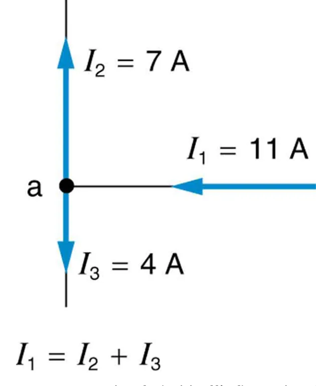 ⤢ Enlarge
Why Kirchhoff’s rules are needed
This section explains the two rules, gives hints for applying them, and works through an example that uses both.
◀ Previous2 / 2
1Take-home experiment: virtual solar cells2Take-home experiment: virtual solar cells
Take-home experiment: virtual solar cells
1
You can model a solar-cell array with playing cards or index cards
where each card stands for one solar cell.
2
Assume each card gives 0.5 V and a current of 2 A under bright light.
3
Cards in series add their voltages, and cards in parallel add their currents.
4
How would you arrange the cards to produce 6 A at 3 V
which is 18 W?
5
Six cards in series give 3 V (6 × 0.5 V).
6
Three such strings in parallel give 6 A (3 × 2 A).
1 / 2Next ▶
Take-home experiment: virtual solar cells
Take-home experiment: virtual solar cells
This uses 18 cards in total.
If you only needed 18 W and no particular voltage, would you need more cards?
No.
Each card supplies 0.5 V × 2 A = 1 W
so 18 cards give 18 W in any series-parallel arrangement that keeps the currents matched.
◀ Previous2 / 2
1Kirchhoff’s first rule (junction rule)2Kirchhoff’s first rule (junction rule)
Kirchhoff’s first rule (junction rule)
Kirchhoff’s first rule (junction rule)
Kirchhoff’s first rule, the junction rule, applies conservation of charge at a junction
which is a point where three or more branches meet.
Current is the flow of charge, and charge is conserved
so the charge that flows into a junction must flow out of it.
The rule is written as: the sum of all currents entering a junction equals the sum of all currents leaving it.
Equations of this form are used to analyze circuits and solve circuit problems.
1 / 2Next ▶
At one junction, 11 A flows in and 7 A and 4 A flow out, so the current entering equals the currents leaving. Image: OpenStax, College Physics for AP Courses 2e, CC BY 4.0.
Kirchhoff’s first rule (junction rule)

◀ Previous2 / 2
1Kirchhoff’s second rule (loop rule)2Kirchhoff’s second rule (loop rule)
Kirchhoff’s second rule (loop rule)
1
Kirchhoff’s second rule, the loop rule, applies conservation of energy.
2
It is stated in terms of electric potential rather than potential energy,
but the two are related,because the potential energy of a charge equals its charge times the potential.
3
The emf of a source is the potential difference across it when no current flows.
4
In a closed loop, all the energy supplied by the emf must be transferred to other forms by the devices in the loop,
because energy cannot enter or leave the circuit any other way.
5
The loop rule says that the algebraic sum of the changes in potential around any closed loop must be zero.
6
Rearranged, this means the emf equals the sum of the IR drops in the loop
where I is the current in amperes and R is the resistance in ohms.
1 / 2Next ▶
In a series loop, the 18 V emf is reduced to zero by 1 V across the internal resistance and 12 V and 5 V across the two load resistors. Image: OpenStax, College Physics for AP Courses 2e, CC BY 4.0.
Kirchhoff’s second rule (loop rule)
 ⤢ Enlarge
Kirchhoff’s second rule (loop rule)
The diagram below shows the potential changes in a simple series loop.
◀ Previous2 / 2
1Applying Kirchhoff’s rules2Applying Kirchhoff’s rules3Applying Kirchhoff’s rules4Applying Kirchhoff’s rules
Applying Kirchhoff’s rules
1
1
2
The unknowns in a circuit may be currents, emfs or resistances.
3
Each time you apply a rule you produce one equation.
4
If there are as many independent equations as unknowns, the problem can be solved.
5
Two decisions control the signs in these equations.
6
2
1 / 4Next ▶
Applying Kirchhoff’s rules
Applying Kirchhoff’s rules
First, when you apply the junction rule, label the current in every branch and choose its direction.
Use arrows to show the directions.
If you choose the wrong direction, the current will have the correct size but a negative sign
so there is no risk in the choice.
3
Second, when you apply the loop rule, pick a closed loop and choose a direction to travel around it, either clockwise or counterclockwise.
Travelling the loop in the opposite direction reverses the sign of every term
which is the same as multiplying the equation by −1.
◀ Previous2 / 4Next ▶
Applying Kirchhoff’s rules
Applying Kirchhoff’s rules
In a circuit that needs more than one loop, you must be consistent about the sign of the potential change in each loop.
4
The sign of each potential change follows four rules, shown in the diagram below. Each element is traversed from point a to point b.
A resistor traversed in the same direction as the current has a potential change of −IR.
A resistor traversed in the direction opposite to the current has a potential change of +IR.
An emf traversed from the negative terminal to the positive terminal (the direction in which it moves positive charge) has a potential change of +ε.
◀ Previous3 / 4Next ▶
The sign of the potential change across a resistor or an emf source, for each direction of travel from a to b. Image: OpenStax, College Physics for AP Courses 2e, CC BY 4.0.
Applying Kirchhoff’s rules
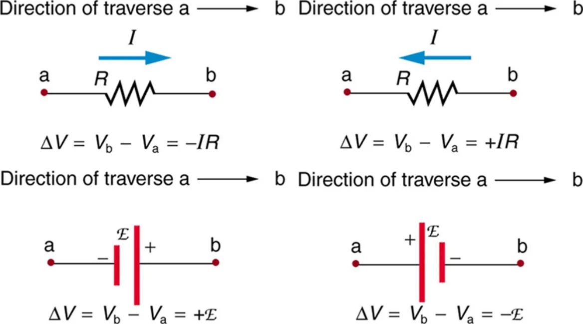 ⤢ Enlarge
Applying Kirchhoff’s rules
An emf traversed from the positive terminal to the negative terminal has a potential change of −ε.
◀ Previous4 / 4
Making connections: conservation laws
Making connections: conservation laws
Kirchhoff’s rules are applications of conservation laws to circuits. The first rule applies conservation of charge, and the second rule applies conservation of energy. Conservation laws are so basic that they form the foundation of circuit analysis, even in a specific application like this one.
1Problem-solving strategies for Kirchhoff’s rules2Problem-solving strategies for Kirchhoff’s rules3Problem-solving strategies for Kirchhoff’s rules
Problem-solving strategies for Kirchhoff’s rules
Problem-solving strategies for Kirchhoff’s rules
1
Draw a clear circuit diagram and label all known and unknown resistances, emfs and currents.
If a current is unknown, assign it a direction
because you need this direction to determine the signs of potential changes.
2
Apply the junction rule at any junction.
Each new application should give an equation that contains a current not seen in an earlier equation.
1 / 3Next ▶
Problem-solving strategies for Kirchhoff’s rules
1
If it does not, the equation is redundant.
2
3
3
Apply the loop rule to as many loops as you need to solve for the unknowns.
4
Choose a direction around each loop and determine the sign of every potential change carefully and consistently, using the four rules above.
5
You must have as many independent equations as unknowns.
6
4
◀ Previous2 / 3Next ▶
Problem-solving strategies for Kirchhoff’s rules
Problem-solving strategies for Kirchhoff’s rules
Solve the simultaneous equations for the unknowns. This can take many algebra steps
so check and recheck your work.
5
Check that the answers are reasonable and consistent.
The values should have sensible orders of magnitude, and no resistance should be negative.
The values should satisfy the equations you wrote, and the currents should satisfy the junction rule.
◀ Previous3 / 3
Discussion: checking with measurements
Discussion: checking with measurements
The rules describe the circuit correctly in theory, and you can verify them by measuring current and voltage. Some of the measuring devices are direct applications of the principles covered so far. An important fact follows from this: making a measurement alters the quantity being measured.
Check your understanding
1
Question: Can Kirchhoff’s rules be applied to simple series and parallel circuits, or are they restricted to more complicated circuits that are not combinations of series and parallel?
2
Answer: Kirchhoff’s rules can be applied to any circuit
because they are applications of two conservation laws, conservation of charge and conservation of energy.
3
These are among the most broadly applicable principles in physics.
4
For simple circuits it is usually mathematically simpler to use the series and parallel rules,
so Kirchhoff’s rules are emphasized for more complicated situations.
5
The series and parallel rules can themselves be derived from Kirchhoff’s rules.
6
Kirchhoff’s rules can also be extended to devices other than resistors and emfs,
such as capacitors,and they are one of the basic analysis tools in circuit analysis.
1Example 21.5: Calculating current using Kirchhoff’s rules2Example 21.5: Calculating current using Kirchhoff’s rules3Example 21.5: Calculating current using Kirchhoff’s rules4Example 21.5: Calculating current using Kirchhoff’s rules5Example 21.5: Calculating current using Kirchhoff’s rules
Example 21.5: Calculating current using Kirchhoff’s rules
1
Find the three currents in the circuit below.
2
The emfs are ε1 = 18 V and ε2 = 45 V.
3
The resistances are R1 = 6.0 Ω, R2 = 2.5 Ω and R3 = 1.5 Ω, and the internal resistances are r1 = 0.5 Ω and r2 = 0.5 Ω.
4
The directions of the currents I1, I2 and I3 are assumed, as shown.
1 / 5Next ▶
The example circuit, with its three branch currents, assumed directions and points a to h labelled. Image: OpenStax, College Physics for AP Courses 2e, CC BY 4.0.
Example 21.5: Calculating current using Kirchhoff’s rules
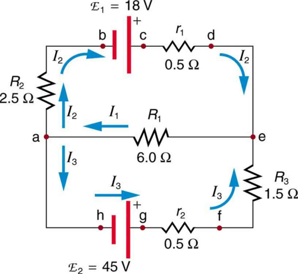 ⤢ Enlarge
Example 21.5: Calculating current using Kirchhoff’s rules
Strategy. The circuit cannot be reduced by Ohm’s law and series-parallel methods
so we use Kirchhoff’s rules. We need three independent equations for the three unknown currents.
Junction rule at a. Current I1 flows into the junction
while I2 and I3 flow outso I1 = I2 + I3. Applying the junction rule at e gives the same equationso it adds no new information. We therefore need the loop rule.
Loop abcdea. Going from a to b through R2 is along the assumed current I2
so the change is −I2R2.
Going from b to c is from the negative to the positive terminal of ε1
so the change is +ε1.
Going from c to d through r1 is along I2
so the change is −I2r1.
Going from d to e is through a wire with no change.
◀ Previous2 / 5Next ▶
Example 21.5: Calculating current using Kirchhoff’s rules
1
Going from e to a through R1 is along I1
so the change is −I1R1.
2
The sum is zero:
3
−I2(2.5 Ω) + 18 V − I2(0.5 Ω) − I1(6.0 Ω) = 0
which gives 3.0 I2 + 6.0 I1 = 18 V.
4
Loop aefgha. Going from a to e through R1 is against I1
so the change is +I1R1.
5
Going from e to f through R3 is against I3
so the change is +I3R3.
6
Going from f to g through r2 is against I3
so the change is +I3r2.
◀ Previous3 / 5Next ▶
Example 21.5: Calculating current using Kirchhoff’s rules
Example 21.5: Calculating current using Kirchhoff’s rules
Going from g to h is from the positive to the negative terminal of ε2
so the change is −ε2.
The signs are opposite to the first loop because the loop is travelled in the opposite direction through these elements:
I1(6.0 Ω) + I3(1.5 Ω + 0.5 Ω) − 45 V = 0
which gives 6.0 I1 + 2.0 I3 = 45 V.
Solving. From the loop equation for abcdea, I2 = 6.0 A − 2.0 I1. From the second loop equation, I3 = 22.5 A − 3.0 I1. Substituting both into the junction equation:
I1 = (6.0 − 2.0 I1) + (22.5 − 3.0 I1) = 28.5 − 5.0 I1
so I1 = 4.75 A.
Then I2 = 6.0 A − 2.0 × 4.75 A = −3.50 A, and I3 = 22.5 A − 3.0 × 4.75 A = 8.25 A.
◀ Previous4 / 5Next ▶
Example 21.5: Calculating current using Kirchhoff’s rules
Example 21.5: Calculating current using Kirchhoff’s rules
The minus sign on I2 means that the current in that branch flows opposite to the direction assumed in the figure.
Check. The junction rule gives 4.75 A = −3.50 A + 8.25 A
which is correct. Substituting into the second loop gives 6.0 × 4.75 + 2.0 × 8.25 = 28.5 + 16.5 = 45 Vwhich is also correct.
◀ Previous5 / 5
Key terms
| Term | Meaning |
|---|---|
| Kirchhoff’s rules | Two rules, based on conservation of charge and energy, that can be used to analyze any circuit, simple or complex. |
| Junction | A point in a circuit where three or more branches meet. |
| Junction rule (first rule) | The sum of all currents entering a junction equals the sum of all currents leaving it, because charge is conserved. |
| Loop | Any closed path through a circuit. |
| Loop rule (second rule) | The algebraic sum of the changes in potential around any closed loop is zero, because energy is conserved. |
| Branch | A section of a circuit between two junctions, which carries a single current. |
| Electromotive force (emf, ε) | The potential difference across a source when no current flows; it is measured in volts (V). |
| Internal resistance (r) | The resistance inside a real source, measured in ohms (Ω), that reduces its terminal voltage when current flows. |
| Conservation of charge | The principle that charge is neither created nor destroyed, so the charge entering a junction must leave it. |
| Conservation of energy | The principle that energy is neither created nor destroyed, so the energy supplied by an emf must be used up around a loop. |
| Photovoltaic generation (PV) | The direct conversion of sunlight into electricity by solar cells, based on the photoelectric effect. |
| Solar-cell array | A group of solar cells connected in series and parallel to give a required voltage and current. |
| Inverter | A device that converts direct current (DC) into alternating current (AC). |
1Avoid these mistakes2Avoid these mistakes3Avoid these mistakes
Avoid these mistakes
1Avoid this
Using the series-parallel methods on a circuit that cannot be reduced to them. Use Kirchhoff’s rules instead.Avoid this
2Avoid this
Assigning the sign of a resistor’s potential change without checking the direction of travel.Avoid this
A resistor traversed along the current gives −IR, and one traversed against the current gives +IR.Avoid this
3Avoid this
1 / 3Next ▶
Avoid these mistakes
Treating an emf as always positive. Traversing an emf from its negative to its positive terminal gives +ε, but from positive to negative gives −ε.Avoid this
4Avoid this
Thinking that a negative current means a calculation error. It means the current flows opposite to the arrow you assumed, with the magnitude shown.Avoid this
5Avoid this
Writing a junction equation that repeats one you already have, such as applying the junction rule at point e after point a.Avoid this
Each new equation must introduce a new current.Avoid this
◀ Previous2 / 3Next ▶
Avoid these mistakes
6Avoid this
Changing the travel direction partway around a loop, or mixing directions between loops, which makes the signs inconsistent.Avoid this
◀ Previous3 / 3