Curriculum
College Physics for AP Courses 2e
Unit 1: Introduction: The Nature of Science and Physics
0/10
-
Unit 1 overview: Introduction: The Nature of Science and Physics
 Text lessonPreview
-
1.1 Physics: An Introduction
Text lessonPreview
-
1.1 Physics: An Introduction - Check yourself
 6 questionsPreview
-
1.2 Physical Quantities and Units
Text lessonPreview
-
1.2 Physical Quantities and Units - Check yourself
6 questionsPreview
-
1.3 Accuracy, Precision, and Significant Figures
Text lessonPreview
-
1.3 Accuracy, Precision, and Significant Figures - Check yourself
6 questionsPreview
-
1.4 Approximation
Text lessonPreview
-
1.4 Approximation - Check yourself
6 questionsPreview
-
Unit 1 review quiz: Introduction: The Nature of Science and Physics
10 questionsPreview
Unit 2: Kinematics
0/18
-
Unit 2 overview: Kinematics
Text lessonPreview
-
2.1 Displacement
Text lessonPreview
-
2.1 Displacement - Check yourself
6 questionsPreview
-
2.2 Vectors, Scalars, and Coordinate Systems
Text lessonPreview
-
2.2 Vectors, Scalars, and Coordinate Systems - Check yourself
6 questionsPreview
-
2.3 Time, Velocity, and Speed
Text lessonPreview
-
2.3 Time, Velocity, and Speed - Check yourself
6 questionsPreview
-
2.4 Acceleration
Text lessonPreview
-
2.4 Acceleration - Check yourself
6 questionsPreview
-
2.5 Motion Equations for Constant Acceleration in One Dimension
Text lessonPreview
-
2.5 Motion Equations for Constant Acceleration in One Dimension - Check yourself
6 questionsPreview
-
2.6 Problem-Solving Basics for One-Dimensional Kinematics
Text lessonPreview
-
2.6 Problem-Solving Basics for One-Dimensional Kinematics - Check yourself
6 questionsPreview
-
2.7 Falling Objects
Text lessonPreview
-
2.7 Falling Objects - Check yourself
6 questionsPreview
-
2.8 Graphical Analysis of One-Dimensional Motion
Text lessonPreview
-
2.8 Graphical Analysis of One-Dimensional Motion - Check yourself
6 questionsPreview
-
Unit 2 review quiz: Kinematics
10 questionsPreview
Unit 3: Two-Dimensional Kinematics
0/12
-
Unit 3 overview: Two-Dimensional Kinematics
Text lessonPreview
-
3.1 Kinematics in Two Dimensions: An Introduction
Text lessonPreview
-
3.1 Kinematics in Two Dimensions: An Introduction - Check yourself
6 questionsPreview
-
3.2 Vector Addition and Subtraction: Graphical Methods
Text lessonPreview
-
3.2 Vector Addition and Subtraction: Graphical Methods - Check yourself
6 questionsPreview
-
3.3 Vector Addition and Subtraction: Analytical Methods
Text lessonPreview
-
3.3 Vector Addition and Subtraction: Analytical Methods - Check yourself
6 questionsPreview
-
3.4 Projectile Motion
Text lessonPreview
-
3.4 Projectile Motion - Check yourself
6 questionsPreview
-
3.5 Addition of Velocities
Text lessonPreview
-
3.5 Addition of Velocities - Check yourself
6 questionsPreview
-
Unit 3 review quiz: Two-Dimensional Kinematics
10 questionsPreview
Unit 4: Dynamics: Force and Newton's Laws of Motion
0/18
-
Unit 4 overview: Dynamics: Force and Newton's Laws of Motion
Text lessonPreview
-
4.1 Development of Force Concept
Text lessonPreview
-
4.1 Development of Force Concept - Check yourself
6 questionsPreview
-
4.2 Newton’s First Law of Motion: Inertia
Text lessonPreview
-
4.2 Newton’s First Law of Motion: Inertia - Check yourself
6 questionsPreview
-
4.3 Newton’s Second Law of Motion: Concept of a System
Text lessonPreview
-
4.3 Newton’s Second Law of Motion: Concept of a System - Check yourself
6 questionsPreview
-
4.4 Newton’s Third Law of Motion: Symmetry in Forces
Text lessonPreview
-
4.4 Newton’s Third Law of Motion: Symmetry in Forces - Check yourself
6 questionsPreview
-
4.5 Normal, Tension, and Other Examples of Forces
Text lessonPreview
-
4.5 Normal, Tension, and Other Examples of Forces - Check yourself
6 questionsPreview
-
4.6 Problem-Solving Strategies
Text lessonPreview
-
4.6 Problem-Solving Strategies - Check yourself
6 questionsPreview
-
4.7 Further Applications of Newton’s Laws of Motion
Text lessonPreview
-
4.7 Further Applications of Newton’s Laws of Motion - Check yourself
6 questionsPreview
-
4.8 Extended Topic: The Four Basic Forces—An Introduction
Text lessonPreview
-
4.8 Extended Topic: The Four Basic Forces—An Introduction - Check yourself
6 questionsPreview
-
Unit 4 review quiz: Dynamics: Force and Newton's Laws of Motion
10 questionsPreview
Unit 5: Further Applications of Newton's Laws: Friction, Drag, and Elasticity
0/8
-
Unit 5 overview: Further Applications of Newton's Laws: Friction, Drag, and Elasticity
Text lessonPreview
-
5.1 Friction
Text lessonPreview
-
5.1 Friction - Check yourself
6 questionsPreview
-
5.2 Drag Forces
Text lessonPreview
-
5.2 Drag Forces - Check yourself
6 questionsPreview
-
5.3 Elasticity: Stress and Strain
Text lessonPreview
-
5.3 Elasticity: Stress and Strain - Check yourself
6 questionsPreview
-
Unit 5 review quiz: Further Applications of Newton's Laws: Friction, Drag, and Elasticity
10 questionsPreview
Unit 6: Uniform Circular Motion and Gravitation
0/14
-
Unit 6 overview: Uniform Circular Motion and Gravitation
Text lessonPreview
-
6.1 Rotation Angle and Angular Velocity
Text lessonPreview
-
6.1 Rotation Angle and Angular Velocity - Check yourself
6 questionsPreview
-
6.2 Centripetal Acceleration
Text lessonPreview
-
6.2 Centripetal Acceleration - Check yourself
6 questionsPreview
-
6.3 Centripetal Force
Text lessonPreview
-
6.3 Centripetal Force - Check yourself
6 questionsPreview
-
6.4 Fictitious Forces and Non-inertial Frames: The Coriolis Force
Text lessonPreview
-
6.4 Fictitious Forces and Non-inertial Frames: The Coriolis Force - Check yourself
6 questionsPreview
-
6.5 Newton’s Universal Law of Gravitation
Text lessonPreview
-
6.5 Newton’s Universal Law of Gravitation - Check yourself
6 questionsPreview
-
6.6 Satellites and Kepler’s Laws: An Argument for Simplicity
Text lessonPreview
-
6.6 Satellites and Kepler’s Laws: An Argument for Simplicity - Check yourself
6 questionsPreview
-
Unit 6 review quiz: Uniform Circular Motion and Gravitation
10 questionsPreview
Unit 7: Work, Energy, and Energy Resources
0/20
-
Unit 7 overview: Work, Energy, and Energy Resources
Text lessonPreview
-
7.1 Work: The Scientific Definition
Text lessonPreview
-
7.1 Work: The Scientific Definition - Check yourself
6 questionsPreview
-
7.2 Kinetic Energy and the Work-Energy Theorem
Text lessonPreview
-
7.2 Kinetic Energy and the Work-Energy Theorem - Check yourself
6 questionsPreview
-
7.3 Gravitational Potential Energy
Text lessonPreview
-
7.3 Gravitational Potential Energy - Check yourself
6 questionsPreview
-
7.4 Conservative Forces and Potential Energy
Text lessonPreview
-
7.4 Conservative Forces and Potential Energy - Check yourself
6 questionsPreview
-
7.5 Nonconservative Forces
Text lessonPreview
-
7.5 Nonconservative Forces - Check yourself
6 questionsPreview
-
7.6 Conservation of Energy
Text lessonPreview
-
7.6 Conservation of Energy - Check yourself
6 questionsPreview
-
7.7 Power
Text lessonPreview
-
7.7 Power - Check yourself
6 questionsPreview
-
7.8 Work, Energy, and Power in Humans
Text lessonPreview
-
7.8 Work, Energy, and Power in Humans - Check yourself
6 questionsPreview
-
7.9 World Energy Use
Text lessonPreview
-
7.9 World Energy Use - Check yourself
6 questionsPreview
-
Unit 7 review quiz: Work, Energy, and Energy Resources
10 questionsPreview
Unit 8: Linear Momentum and Collisions
0/32
-
Unit 8 overview: Linear Momentum and Collisions
Text lessonPreview
-
8.1 Linear Momentum and Force
Text lessonPreview
-
8.1 Linear Momentum and Force - Check yourself
6 questionsPreview
-
8.1 Linear Momentum and Force
Text lessonPreview
-
8.1 Linear Momentum and Force - Check yourself
6 questionsPreview
-
8.2 Impulse
Text lessonPreview
-
8.2 Impulse - Check yourself
6 questionsPreview
-
8.2 Impulse
Text lessonPreview
-
8.2 Impulse - Check yourself
6 questionsPreview
-
8.3 Conservation of Momentum
Text lessonPreview
-
8.3 Conservation of Momentum - Check yourself
6 questionsPreview
-
8.3 Conservation of Momentum
Text lessonPreview
-
8.3 Conservation of Momentum - Check yourself
6 questionsPreview
-
8.4 Elastic Collisions in One Dimension
Text lessonPreview
-
8.4 Elastic Collisions in One Dimension - Check yourself
6 questionsPreview
-
Unit 8 review quiz: Linear Momentum and Collisions
10 questionsPreview
-
Unit 8 overview: Linear Momentum and Collisions
Text lessonPreview
-
8.4 Elastic Collisions in One Dimension
Text lessonPreview
-
8.4 Elastic Collisions in One Dimension - Check yourself
6 questionsPreview
-
8.5 Inelastic Collisions in One Dimension
Text lessonPreview
-
8.5 Inelastic Collisions in One Dimension - Check yourself
6 questionsPreview
-
8.5 Inelastic Collisions in One Dimension
Text lessonPreview
-
8.5 Inelastic Collisions in One Dimension - Check yourself
6 questionsPreview
-
8.6 Collisions of Point Masses in Two Dimensions
Text lessonPreview
-
8.6 Collisions of Point Masses in Two Dimensions - Check yourself
6 questionsPreview
-
8.6 Collisions of Point Masses in Two Dimensions
Text lessonPreview
-
8.6 Collisions of Point Masses in Two Dimensions - Check yourself
6 questionsPreview
-
8.7 Introduction to Rocket Propulsion
Text lessonPreview
-
8.7 Introduction to Rocket Propulsion - Check yourself
6 questionsPreview
-
8.7 Introduction to Rocket Propulsion
Text lessonPreview
-
8.7 Introduction to Rocket Propulsion - Check yourself
6 questionsPreview
-
Unit 8 review quiz: Linear Momentum and Collisions
10 questionsPreview
Unit 9: Statics and Torque
0/28
-
Unit 9 overview: Statics and Torque
Text lessonPreview
-
9.1 The First Condition for Equilibrium
Text lessonPreview
-
9.1 The First Condition for Equilibrium - Check yourself
6 questionsPreview
-
9.1 The First Condition for Equilibrium
Text lessonPreview
-
9.1 The First Condition for Equilibrium - Check yourself
6 questionsPreview
-
9.2 The Second Condition for Equilibrium
Text lessonPreview
-
9.2 The Second Condition for Equilibrium - Check yourself
6 questionsPreview
-
9.2 The Second Condition for Equilibrium
Text lessonPreview
-
9.2 The Second Condition for Equilibrium - Check yourself
6 questionsPreview
-
9.3 Stability
Text lessonPreview
-
9.3 Stability - Check yourself
6 questionsPreview
-
9.3 Stability
Text lessonPreview
-
9.3 Stability - Check yourself
6 questionsPreview
-
Unit 9 review quiz: Statics and Torque
10 questionsPreview
-
Unit 9 overview: Statics and Torque
Text lessonPreview
-
9.4 Applications of Statics, Including Problem-Solving Strategies
Text lessonPreview
-
9.4 Applications of Statics, Including Problem-Solving Strategies - Check yourself
6 questionsPreview
-
9.4 Applications of Statics, Including Problem-Solving Strategies
Text lessonPreview
-
9.4 Applications of Statics, Including Problem-Solving Strategies - Check yourself
6 questionsPreview
-
9.5 Simple Machines
Text lessonPreview
-
9.5 Simple Machines - Check yourself
6 questionsPreview
-
9.5 Simple Machines
Text lessonPreview
-
9.5 Simple Machines - Check yourself
6 questionsPreview
-
9.6 Forces and Torques in Muscles and Joints
Text lessonPreview
-
9.6 Forces and Torques in Muscles and Joints - Check yourself
6 questionsPreview
-
9.6 Forces and Torques in Muscles and Joints
Text lessonPreview
-
9.6 Forces and Torques in Muscles and Joints - Check yourself
6 questionsPreview
-
Unit 9 review quiz: Statics and Torque
10 questionsPreview
Unit 10: Rotational Motion and Angular Momentum
0/32
-
Unit 10 overview: Rotational Motion and Angular Momentum
Text lessonPreview
-
10.1 Angular Acceleration
Text lessonPreview
-
10.1 Angular Acceleration - Check yourself
6 questionsPreview
-
10.1 Angular Acceleration
Text lessonPreview
-
10.1 Angular Acceleration - Check yourself
6 questionsPreview
-
10.2 Kinematics of Rotational Motion
Text lessonPreview
-
10.2 Kinematics of Rotational Motion - Check yourself
6 questionsPreview
-
10.2 Kinematics of Rotational Motion
Text lessonPreview
-
10.2 Kinematics of Rotational Motion - Check yourself
6 questionsPreview
-
10.3 Dynamics of Rotational Motion: Rotational Inertia
Text lessonPreview
-
10.3 Dynamics of Rotational Motion: Rotational Inertia - Check yourself
6 questionsPreview
-
10.3 Dynamics of Rotational Motion: Rotational Inertia
Text lessonPreview
-
10.3 Dynamics of Rotational Motion: Rotational Inertia - Check yourself
6 questionsPreview
-
10.4 Rotational Kinetic Energy: Work and Energy Revisited
Text lessonPreview
-
10.4 Rotational Kinetic Energy: Work and Energy Revisited - Check yourself
6 questionsPreview
-
Unit 10 review quiz: Rotational Motion and Angular Momentum
10 questionsPreview
-
Unit 10 overview: Rotational Motion and Angular Momentum
Text lessonPreview
-
10.4 Rotational Kinetic Energy: Work and Energy Revisited
Text lessonPreview
-
10.4 Rotational Kinetic Energy: Work and Energy Revisited - Check yourself
6 questionsPreview
-
10.5 Angular Momentum and Its Conservation
Text lessonPreview
-
10.5 Angular Momentum and Its Conservation - Check yourself
6 questionsPreview
-
10.5 Angular Momentum and Its Conservation
Text lessonPreview
-
10.5 Angular Momentum and Its Conservation - Check yourself
6 questionsPreview
-
10.6 Collisions of Extended Bodies in Two Dimensions
Text lessonPreview
-
10.6 Collisions of Extended Bodies in Two Dimensions - Check yourself
6 questionsPreview
-
10.6 Collisions of Extended Bodies in Two Dimensions
Text lessonPreview
-
10.6 Collisions of Extended Bodies in Two Dimensions - Check yourself
6 questionsPreview
-
10.7 Gyroscopic Effects: Vector Aspects of Angular Momentum
Text lessonPreview
-
10.7 Gyroscopic Effects: Vector Aspects of Angular Momentum - Check yourself
6 questionsPreview
-
10.7 Gyroscopic Effects: Vector Aspects of Angular Momentum
Text lessonPreview
-
10.7 Gyroscopic Effects: Vector Aspects of Angular Momentum - Check yourself
6 questionsPreview
-
Unit 10 review quiz: Rotational Motion and Angular Momentum
10 questionsPreview
Unit 11: Fluid Statics
0/40
-
Unit 11 overview: Fluid Statics
Text lessonPreview
-
11.1 What Is a Fluid?
Text lessonPreview
-
11.1 What Is a Fluid? - Check yourself
6 questionsPreview
-
11.1 What Is a Fluid?
Text lessonPreview
-
11.1 What Is a Fluid? - Check yourself
6 questionsPreview
-
11.2 Density
Text lessonPreview
-
11.2 Density - Check yourself
6 questionsPreview
-
11.2 Density
Text lessonPreview
-
11.2 Density - Check yourself
6 questionsPreview
-
11.3 Pressure
Text lessonPreview
-
11.3 Pressure - Check yourself
6 questionsPreview
-
11.3 Pressure
Text lessonPreview
-
11.3 Pressure - Check yourself
6 questionsPreview
-
11.4 Variation of Pressure with Depth in a Fluid
Text lessonPreview
-
11.4 Variation of Pressure with Depth in a Fluid - Check yourself
6 questionsPreview
-
11.4 Variation of Pressure with Depth in a Fluid
Text lessonPreview
-
11.4 Variation of Pressure with Depth in a Fluid - Check yourself
6 questionsPreview
-
11.5 Pascal’s Principle
Text lessonPreview
-
11.5 Pascal’s Principle - Check yourself
6 questionsPreview
-
Unit 11 review quiz: Fluid Statics
10 questionsPreview
-
Unit 11 overview: Fluid Statics
Text lessonPreview
-
11.5 Pascal’s Principle
Text lessonPreview
-
11.5 Pascal’s Principle - Check yourself
6 questionsPreview
-
11.6 Gauge Pressure, Absolute Pressure, and Pressure Measurement
Text lessonPreview
-
11.6 Gauge Pressure, Absolute Pressure, and Pressure Measurement - Check yourself
6 questionsPreview
-
11.6 Gauge Pressure, Absolute Pressure, and Pressure Measurement
Text lessonPreview
-
11.6 Gauge Pressure, Absolute Pressure, and Pressure Measurement - Check yourself
6 questionsPreview
-
11.7 Archimedes’ Principle
Text lessonPreview
-
11.7 Archimedes’ Principle - Check yourself
6 questionsPreview
-
11.7 Archimedes’ Principle
Text lessonPreview
-
11.7 Archimedes’ Principle - Check yourself
6 questionsPreview
-
11.8 Cohesion and Adhesion in Liquids: Surface Tension and Capillary Action
Text lessonPreview
-
11.8 Cohesion and Adhesion in Liquids: Surface Tension and Capillary Action - Check yourself
6 questionsPreview
-
11.8 Cohesion and Adhesion in Liquids: Surface Tension and Capillary Action
Text lessonPreview
-
11.8 Cohesion and Adhesion in Liquids: Surface Tension and Capillary Action - Check yourself
6 questionsPreview
-
11.9 Pressures in the Body
Text lessonPreview
-
11.9 Pressures in the Body - Check yourself
6 questionsPreview
-
11.9 Pressures in the Body
Text lessonPreview
-
11.9 Pressures in the Body - Check yourself
6 questionsPreview
-
Unit 11 review quiz: Fluid Statics
10 questionsPreview
Unit 12: Fluid Dynamics and Its Biological and Medical Applications
0/32
-
Unit 12 overview: Fluid Dynamics and Its Biological and Medical Applications
Text lessonPreview
-
12.1 Flow Rate and Its Relation to Velocity
Text lessonPreview
-
12.1 Flow Rate and Its Relation to Velocity - Check yourself
6 questionsPreview
-
12.1 Flow Rate and Its Relation to Velocity
Text lessonPreview
-
12.1 Flow Rate and Its Relation to Velocity - Check yourself
6 questionsPreview
-
12.2 Bernoulli’s Equation
Text lessonPreview
-
12.2 Bernoulli’s Equation - Check yourself
6 questionsPreview
-
12.2 Bernoulli’s Equation
Text lessonPreview
-
12.2 Bernoulli’s Equation - Check yourself
6 questionsPreview
-
12.3 The Most General Applications of Bernoulli’s Equation
Text lessonPreview
-
12.3 The Most General Applications of Bernoulli’s Equation - Check yourself
6 questionsPreview
-
12.3 The Most General Applications of Bernoulli’s Equation
Text lessonPreview
-
12.3 The Most General Applications of Bernoulli’s Equation - Check yourself
6 questionsPreview
-
12.4 Viscosity and Laminar Flow; Poiseuille’s Law
Text lessonPreview
-
12.4 Viscosity and Laminar Flow; Poiseuille’s Law - Check yourself
6 questionsPreview
-
Unit 12 review quiz: Fluid Dynamics and Its Biological and Medical Applications
10 questionsPreview
-
Unit 12 overview: Fluid Dynamics and Its Biological and Medical Applications
Text lessonPreview
-
12.4 Viscosity and Laminar Flow; Poiseuille’s Law
Text lessonPreview
-
12.4 Viscosity and Laminar Flow; Poiseuille’s Law - Check yourself
6 questionsPreview
-
12.5 The Onset of Turbulence
Text lessonPreview
-
12.5 The Onset of Turbulence - Check yourself
6 questionsPreview
-
12.5 The Onset of Turbulence
Text lessonPreview
-
12.5 The Onset of Turbulence - Check yourself
6 questionsPreview
-
12.6 Motion of an Object in a Viscous Fluid
Text lessonPreview
-
12.6 Motion of an Object in a Viscous Fluid - Check yourself
6 questionsPreview
-
12.6 Motion of an Object in a Viscous Fluid
Text lessonPreview
-
12.6 Motion of an Object in a Viscous Fluid - Check yourself
6 questionsPreview
-
12.7 Molecular Transport Phenomena: Diffusion, Osmosis, and Related Processes
Text lessonPreview
-
12.7 Molecular Transport Phenomena: Diffusion, Osmosis, and Related Processes - Check yourself
6 questionsPreview
-
12.7 Molecular Transport Phenomena: Diffusion, Osmosis, and Related Processes
Text lessonPreview
-
12.7 Molecular Transport Phenomena: Diffusion, Osmosis, and Related Processes - Check yourself
6 questionsPreview
-
Unit 12 review quiz: Fluid Dynamics and Its Biological and Medical Applications
10 questionsPreview
Unit 13: Temperature, Kinetic Theory, and the Gas Laws
0/28
-
Unit 13 overview: Temperature, Kinetic Theory, and the Gas Laws
Text lessonPreview
-
13.1 Temperature
Text lessonPreview
-
13.1 Temperature - Check yourself
6 questionsPreview
-
13.1 Temperature
Text lessonPreview
-
13.1 Temperature - Check yourself
6 questionsPreview
-
13.2 Thermal Expansion of Solids and Liquids
Text lessonPreview
-
13.2 Thermal Expansion of Solids and Liquids - Check yourself
6 questionsPreview
-
13.2 Thermal Expansion of Solids and Liquids
Text lessonPreview
-
13.2 Thermal Expansion of Solids and Liquids - Check yourself
6 questionsPreview
-
13.3 The Ideal Gas Law
Text lessonPreview
-
13.3 The Ideal Gas Law - Check yourself
6 questionsPreview
-
13.3 The Ideal Gas Law
Text lessonPreview
-
13.3 The Ideal Gas Law - Check yourself
6 questionsPreview
-
Unit 13 review quiz: Temperature, Kinetic Theory, and the Gas Laws
10 questionsPreview
-
Unit 13 overview: Temperature, Kinetic Theory, and the Gas Laws
Text lessonPreview
-
13.4 Kinetic Theory: Atomic and Molecular Explanation of Pressure and Temperature
Text lessonPreview
-
13.4 Kinetic Theory: Atomic and Molecular Explanation of Pressure and Temperature - Check yourself
6 questionsPreview
-
13.4 Kinetic Theory: Atomic and Molecular Explanation of Pressure and Temperature
Text lessonPreview
-
13.4 Kinetic Theory: Atomic and Molecular Explanation of Pressure and Temperature - Check yourself
6 questionsPreview
-
13.5 Phase Changes
Text lessonPreview
-
13.5 Phase Changes - Check yourself
6 questionsPreview
-
13.5 Phase Changes
Text lessonPreview
-
13.5 Phase Changes - Check yourself
6 questionsPreview
-
13.6 Humidity, Evaporation, and Boiling
Text lessonPreview
-
13.6 Humidity, Evaporation, and Boiling - Check yourself
6 questionsPreview
-
13.6 Humidity, Evaporation, and Boiling
Text lessonPreview
-
13.6 Humidity, Evaporation, and Boiling - Check yourself
6 questionsPreview
-
Unit 13 review quiz: Temperature, Kinetic Theory, and the Gas Laws
10 questionsPreview
Unit 14: Heat and Heat Transfer Methods
0/32
-
Unit 14 overview: Heat and Heat Transfer Methods
Text lessonPreview
-
14.1 Heat
Text lessonPreview
-
14.1 Heat - Check yourself
6 questionsPreview
-
14.1 Heat
Text lessonPreview
-
14.1 Heat - Check yourself
6 questionsPreview
-
14.2 Temperature Change and Heat Capacity
Text lessonPreview
-
14.2 Temperature Change and Heat Capacity - Check yourself
6 questionsPreview
-
14.2 Temperature Change and Heat Capacity
Text lessonPreview
-
14.2 Temperature Change and Heat Capacity - Check yourself
6 questionsPreview
-
14.3 Phase Change and Latent Heat
Text lessonPreview
-
14.3 Phase Change and Latent Heat - Check yourself
6 questionsPreview
-
14.3 Phase Change and Latent Heat
Text lessonPreview
-
14.3 Phase Change and Latent Heat - Check yourself
6 questionsPreview
-
14.4 Heat Transfer Methods
Text lessonPreview
-
14.4 Heat Transfer Methods - Check yourself
6 questionsPreview
-
Unit 14 review quiz: Heat and Heat Transfer Methods
10 questionsPreview
-
Unit 14 overview: Heat and Heat Transfer Methods
Text lessonPreview
-
14.4 Heat Transfer Methods
Text lessonPreview
-
14.4 Heat Transfer Methods - Check yourself
6 questionsPreview
-
14.5 Conduction
Text lessonPreview
-
14.5 Conduction - Check yourself
6 questionsPreview
-
14.5 Conduction
Text lessonPreview
-
14.5 Conduction - Check yourself
6 questionsPreview
-
14.6 Convection
Text lessonPreview
-
14.6 Convection - Check yourself
6 questionsPreview
-
14.6 Convection
Text lessonPreview
-
14.6 Convection - Check yourself
6 questionsPreview
-
14.7 Radiation
Text lessonPreview
-
14.7 Radiation - Check yourself
6 questionsPreview
-
14.7 Radiation
Text lessonPreview
-
14.7 Radiation - Check yourself
6 questionsPreview
-
Unit 14 review quiz: Heat and Heat Transfer Methods
10 questionsPreview
Unit 15: Thermodynamics
0/32
-
Unit 15 overview: Thermodynamics
Text lessonPreview
-
15.1 The First Law of Thermodynamics
Text lessonPreview
-
15.1 The First Law of Thermodynamics - Check yourself
6 questionsPreview
-
15.1 The First Law of Thermodynamics
Text lessonPreview
-
15.1 The First Law of Thermodynamics - Check yourself
6 questionsPreview
-
15.2 The First Law of Thermodynamics and Some Simple Processes
Text lessonPreview
-
15.2 The First Law of Thermodynamics and Some Simple Processes - Check yourself
6 questionsPreview
-
15.2 The First Law of Thermodynamics and Some Simple Processes
Text lessonPreview
-
15.2 The First Law of Thermodynamics and Some Simple Processes - Check yourself
6 questionsPreview
-
15.3 Introduction to the Second Law of Thermodynamics: Heat Engines and Their Efficiency
Text lessonPreview
-
15.3 Introduction to the Second Law of Thermodynamics: Heat Engines and Their Efficiency - Check yourself
6 questionsPreview
-
15.3 Introduction to the Second Law of Thermodynamics: Heat Engines and Their Efficiency
Text lessonPreview
-
15.3 Introduction to the Second Law of Thermodynamics: Heat Engines and Their Efficiency - Check yourself
6 questionsPreview
-
15.4 Carnot’s Perfect Heat Engine: The Second Law of Thermodynamics Restated
Text lessonPreview
-
15.4 Carnot’s Perfect Heat Engine: The Second Law of Thermodynamics Restated - Check yourself
6 questionsPreview
-
Unit 15 review quiz: Thermodynamics
10 questionsPreview
-
Unit 15 overview: Thermodynamics
Text lessonPreview
-
15.4 Carnot’s Perfect Heat Engine: The Second Law of Thermodynamics Restated
Text lessonPreview
-
15.4 Carnot’s Perfect Heat Engine: The Second Law of Thermodynamics Restated - Check yourself
6 questionsPreview
-
15.5 Applications of Thermodynamics: Heat Pumps and Refrigerators
Text lessonPreview
-
15.5 Applications of Thermodynamics: Heat Pumps and Refrigerators - Check yourself
6 questionsPreview
-
15.5 Applications of Thermodynamics: Heat Pumps and Refrigerators
Text lessonPreview
-
15.5 Applications of Thermodynamics: Heat Pumps and Refrigerators - Check yourself
6 questionsPreview
-
15.6 Entropy and the Second Law of Thermodynamics: Disorder and the Unavailability of Energy
Text lessonPreview
-
15.6 Entropy and the Second Law of Thermodynamics: Disorder and the Unavailability of Energy - Check yourself
6 questionsPreview
-
15.6 Entropy and the Second Law of Thermodynamics: Disorder and the Unavailability of Energy
Text lessonPreview
-
15.6 Entropy and the Second Law of Thermodynamics: Disorder and the Unavailability of Energy - Check yourself
6 questionsPreview
-
15.7 Statistical Interpretation of Entropy and the Second Law of Thermodynamics: The Underlying Explanation
Text lessonPreview
-
15.7 Statistical Interpretation of Entropy and the Second Law of Thermodynamics: The Underlying Explanation - Check yourself
6 questionsPreview
-
15.7 Statistical Interpretation of Entropy and the Second Law of Thermodynamics: The Underlying Explanation
Text lessonPreview
-
15.7 Statistical Interpretation of Entropy and the Second Law of Thermodynamics: The Underlying Explanation - Check yourself
6 questionsPreview
-
Unit 15 review quiz: Thermodynamics
10 questionsPreview
Unit 16: Oscillatory Motion and Waves
0/48
-
Unit 16 overview: Oscillatory Motion and Waves
Text lessonPreview
-
16.1 Hooke’s Law: Stress and Strain Revisited
Text lessonPreview
-
16.1 Hooke’s Law: Stress and Strain Revisited - Check yourself
6 questionsPreview
-
16.1 Hooke’s Law: Stress and Strain Revisited
Text lessonPreview
-
16.1 Hooke’s Law: Stress and Strain Revisited - Check yourself
6 questionsPreview
-
16.2 Period and Frequency in Oscillations
Text lessonPreview
-
16.2 Period and Frequency in Oscillations - Check yourself
6 questionsPreview
-
16.2 Period and Frequency in Oscillations
Text lessonPreview
-
16.2 Period and Frequency in Oscillations - Check yourself
6 questionsPreview
-
16.3 Simple Harmonic Motion: A Special Periodic Motion
Text lessonPreview
-
16.3 Simple Harmonic Motion: A Special Periodic Motion - Check yourself
6 questionsPreview
-
16.3 Simple Harmonic Motion: A Special Periodic Motion
Text lessonPreview
-
16.3 Simple Harmonic Motion: A Special Periodic Motion - Check yourself
6 questionsPreview
-
16.4 The Simple Pendulum
Text lessonPreview
-
16.4 The Simple Pendulum - Check yourself
6 questionsPreview
-
16.4 The Simple Pendulum
Text lessonPreview
-
16.4 The Simple Pendulum - Check yourself
6 questionsPreview
-
16.5 Energy and the Simple Harmonic Oscillator
Text lessonPreview
-
16.5 Energy and the Simple Harmonic Oscillator - Check yourself
6 questionsPreview
-
16.5 Energy and the Simple Harmonic Oscillator
Text lessonPreview
-
16.5 Energy and the Simple Harmonic Oscillator - Check yourself
6 questionsPreview
-
16.6 Uniform Circular Motion and Simple Harmonic Motion
Text lessonPreview
-
16.6 Uniform Circular Motion and Simple Harmonic Motion - Check yourself
6 questionsPreview
-
Unit 16 review quiz: Oscillatory Motion and Waves
10 questionsPreview
-
Unit 16 overview: Oscillatory Motion and Waves
Text lessonPreview
-
16.6 Uniform Circular Motion and Simple Harmonic Motion
Text lessonPreview
-
16.6 Uniform Circular Motion and Simple Harmonic Motion - Check yourself
6 questionsPreview
-
16.7 Damped Harmonic Motion
Text lessonPreview
-
16.7 Damped Harmonic Motion - Check yourself
6 questionsPreview
-
16.7 Damped Harmonic Motion
Text lessonPreview
-
16.7 Damped Harmonic Motion - Check yourself
6 questionsPreview
-
16.8 Forced Oscillations and Resonance
Text lessonPreview
-
16.8 Forced Oscillations and Resonance - Check yourself
6 questionsPreview
-
16.8 Forced Oscillations and Resonance
Text lessonPreview
-
16.8 Forced Oscillations and Resonance - Check yourself
6 questionsPreview
-
16.9 Waves
Text lessonPreview
-
16.9 Waves - Check yourself
6 questionsPreview
-
16.9 Waves
Text lessonPreview
-
16.9 Waves - Check yourself
6 questionsPreview
-
16.10 Superposition and Interference
Text lessonPreview
-
16.10 Superposition and Interference - Check yourself
6 questionsPreview
-
16.10 Superposition and Interference
Text lessonPreview
-
16.10 Superposition and Interference - Check yourself
6 questionsPreview
-
16.11 Energy in Waves: Intensity
Text lessonPreview
-
16.11 Energy in Waves: Intensity - Check yourself
6 questionsPreview
-
16.11 Energy in Waves: Intensity
Text lessonPreview
-
16.11 Energy in Waves: Intensity - Check yourself
6 questionsPreview
-
Unit 16 review quiz: Oscillatory Motion and Waves
10 questionsPreview
Unit 17: Physics of Hearing
0/32
-
Unit 17 overview: Physics of Hearing
Text lessonPreview
-
17.1 Sound
Text lessonPreview
-
17.1 Sound - Check yourself
6 questionsPreview
-
17.1 Sound
Text lessonPreview
-
17.1 Sound - Check yourself
6 questionsPreview
-
17.2 Speed of Sound, Frequency, and Wavelength
Text lessonPreview
-
17.2 Speed of Sound, Frequency, and Wavelength - Check yourself
6 questionsPreview
-
17.2 Speed of Sound, Frequency, and Wavelength
Text lessonPreview
-
17.2 Speed of Sound, Frequency, and Wavelength - Check yourself
6 questionsPreview
-
17.3 Sound Intensity and Sound Level
Text lessonPreview
-
17.3 Sound Intensity and Sound Level - Check yourself
6 questionsPreview
-
17.3 Sound Intensity and Sound Level
Text lessonPreview
-
17.3 Sound Intensity and Sound Level - Check yourself
6 questionsPreview
-
17.4 Doppler Effect and Sonic Booms
Text lessonPreview
-
17.4 Doppler Effect and Sonic Booms - Check yourself
6 questionsPreview
-
Unit 17 review quiz: Physics of Hearing
10 questionsPreview
-
Unit 17 overview: Physics of Hearing
Text lessonPreview
-
17.4 Doppler Effect and Sonic Booms
Text lessonPreview
-
17.4 Doppler Effect and Sonic Booms - Check yourself
6 questionsPreview
-
17.5 Sound Interference and Resonance: Standing Waves in Air Columns
Text lessonPreview
-
17.5 Sound Interference and Resonance: Standing Waves in Air Columns - Check yourself
6 questionsPreview
-
17.5 Sound Interference and Resonance: Standing Waves in Air Columns
Text lessonPreview
-
17.5 Sound Interference and Resonance: Standing Waves in Air Columns - Check yourself
6 questionsPreview
-
17.6 Hearing
Text lessonPreview
-
17.6 Hearing - Check yourself
6 questionsPreview
-
17.6 Hearing
Text lessonPreview
-
17.6 Hearing - Check yourself
6 questionsPreview
-
17.7 Ultrasound
Text lessonPreview
-
17.7 Ultrasound - Check yourself
6 questionsPreview
-
17.7 Ultrasound
Text lessonPreview
-
17.7 Ultrasound - Check yourself
6 questionsPreview
-
Unit 17 review quiz: Physics of Hearing
10 questionsPreview
Unit 18: Electric Charge and Electric Field
0/36
-
Unit 18 overview: Electric Charge and Electric Field
Text lessonPreview
-
18.1 Static Electricity and Charge: Conservation of Charge
Text lessonPreview
-
18.1 Static Electricity and Charge: Conservation of Charge - Check yourself
6 questionsPreview
-
18.1 Static Electricity and Charge: Conservation of Charge
Text lessonPreview
-
18.1 Static Electricity and Charge: Conservation of Charge - Check yourself
6 questionsPreview
-
18.2 Conductors and Insulators
Text lessonPreview
-
18.2 Conductors and Insulators - Check yourself
6 questionsPreview
-
18.2 Conductors and Insulators
Text lessonPreview
-
18.2 Conductors and Insulators - Check yourself
6 questionsPreview
-
18.3 Conductors and Electric Fields in Static Equilibrium
Text lessonPreview
-
18.3 Conductors and Electric Fields in Static Equilibrium - Check yourself
6 questionsPreview
-
18.3 Conductors and Electric Fields in Static Equilibrium
Text lessonPreview
-
18.3 Conductors and Electric Fields in Static Equilibrium - Check yourself
6 questionsPreview
-
18.4 Coulomb’s Law
Text lessonPreview
-
18.4 Coulomb’s Law - Check yourself
6 questionsPreview
-
18.4 Coulomb’s Law
Text lessonPreview
-
18.4 Coulomb’s Law - Check yourself
6 questionsPreview
-
Unit 18 review quiz: Electric Charge and Electric Field
10 questionsPreview
-
Unit 18 overview: Electric Charge and Electric Field
Text lessonPreview
-
18.5 Electric Field: Concept of a Field Revisited
Text lessonPreview
-
18.5 Electric Field: Concept of a Field Revisited - Check yourself
6 questionsPreview
-
18.5 Electric Field: Concept of a Field Revisited
Text lessonPreview
-
18.5 Electric Field: Concept of a Field Revisited - Check yourself
6 questionsPreview
-
18.6 Electric Field Lines: Multiple Charges
Text lessonPreview
-
18.6 Electric Field Lines: Multiple Charges - Check yourself
6 questionsPreview
-
18.6 Electric Field Lines: Multiple Charges
Text lessonPreview
-
18.6 Electric Field Lines: Multiple Charges - Check yourself
6 questionsPreview
-
18.7 Electric Forces in Biology
Text lessonPreview
-
18.7 Electric Forces in Biology - Check yourself
6 questionsPreview
-
18.7 Electric Forces in Biology
Text lessonPreview
-
18.7 Electric Forces in Biology - Check yourself
6 questionsPreview
-
18.8 Applications of Electrostatics
Text lessonPreview
-
18.8 Applications of Electrostatics - Check yourself
6 questionsPreview
-
18.8 Applications of Electrostatics
Text lessonPreview
-
18.8 Applications of Electrostatics - Check yourself
6 questionsPreview
-
Unit 18 review quiz: Electric Charge and Electric Field
10 questionsPreview
Unit 19: Electric Potential and Electric Field
0/32
-
Unit 19 overview: Electric Potential and Electric Field
Text lessonPreview
-
19.1 Electric Potential Energy: Potential Difference
Text lessonPreview
-
19.1 Electric Potential Energy: Potential Difference - Check yourself
6 questionsPreview
-
19.1 Electric Potential Energy: Potential Difference
Text lessonPreview
-
19.1 Electric Potential Energy: Potential Difference - Check yourself
6 questionsPreview
-
19.2 Electric Potential in a Uniform Electric Field
Text lessonPreview
-
19.2 Electric Potential in a Uniform Electric Field - Check yourself
6 questionsPreview
-
19.2 Electric Potential in a Uniform Electric Field
Text lessonPreview
-
19.2 Electric Potential in a Uniform Electric Field - Check yourself
6 questionsPreview
-
19.3 Electrical Potential Due to a Point Charge
Text lessonPreview
-
19.3 Electrical Potential Due to a Point Charge - Check yourself
6 questionsPreview
-
19.3 Electrical Potential Due to a Point Charge
Text lessonPreview
-
19.3 Electrical Potential Due to a Point Charge - Check yourself
6 questionsPreview
-
19.4 Equipotential Lines
Text lessonPreview
-
19.4 Equipotential Lines - Check yourself
6 questionsPreview
-
Unit 19 review quiz: Electric Potential and Electric Field
10 questionsPreview
-
Unit 19 overview: Electric Potential and Electric Field
Text lessonPreview
-
19.4 Equipotential Lines
Text lessonPreview
-
19.4 Equipotential Lines - Check yourself
6 questionsPreview
-
19.5 Capacitors and Dielectrics
Text lessonPreview
-
19.5 Capacitors and Dielectrics - Check yourself
6 questionsPreview
-
19.5 Capacitors and Dielectrics
Text lessonPreview
-
19.5 Capacitors and Dielectrics - Check yourself
6 questionsPreview
-
19.6 Capacitors in Series and Parallel
Text lessonPreview
-
19.6 Capacitors in Series and Parallel - Check yourself
6 questionsPreview
-
19.6 Capacitors in Series and Parallel
Text lessonPreview
-
19.6 Capacitors in Series and Parallel - Check yourself
6 questionsPreview
-
19.7 Energy Stored in Capacitors
Text lessonPreview
-
19.7 Energy Stored in Capacitors - Check yourself
6 questionsPreview
-
19.7 Energy Stored in Capacitors
Text lessonPreview
-
19.7 Energy Stored in Capacitors - Check yourself
6 questionsPreview
-
Unit 19 review quiz: Electric Potential and Electric Field
10 questionsPreview
Unit 20: Electric Current, Resistance, and Ohm's Law
0/32
-
Unit 20 overview: Electric Current, Resistance, and Ohm's Law
Text lessonPreview
-
20.1 Current
Text lessonPreview
-
20.1 Current - Check yourself
6 questionsPreview
-
20.1 Current
Text lessonPreview
-
20.1 Current - Check yourself
6 questionsPreview
-
20.2 Ohm’s Law: Resistance and Simple Circuits
Text lessonPreview
-
20.2 Ohm’s Law: Resistance and Simple Circuits - Check yourself
6 questionsPreview
-
20.2 Ohm’s Law: Resistance and Simple Circuits
Text lessonPreview
-
20.2 Ohm’s Law: Resistance and Simple Circuits - Check yourself
6 questionsPreview
-
20.3 Resistance and Resistivity
Text lessonPreview
-
20.3 Resistance and Resistivity - Check yourself
6 questionsPreview
-
20.3 Resistance and Resistivity
Text lessonPreview
-
20.3 Resistance and Resistivity - Check yourself
6 questionsPreview
-
20.4 Electric Power and Energy
Text lessonPreview
-
20.4 Electric Power and Energy - Check yourself
6 questionsPreview
-
Unit 20 review quiz: Electric Current, Resistance, and Ohm's Law
10 questionsPreview
-
Unit 20 overview: Electric Current, Resistance, and Ohm's Law
Text lessonPreview
-
20.4 Electric Power and Energy
Text lessonPreview
-
20.4 Electric Power and Energy - Check yourself
6 questionsPreview
-
20.5 Alternating Current versus Direct Current
Text lessonPreview
-
20.5 Alternating Current versus Direct Current - Check yourself
6 questionsPreview
-
20.5 Alternating Current versus Direct Current
Text lessonPreview
-
20.5 Alternating Current versus Direct Current - Check yourself
6 questionsPreview
-
20.6 Electric Hazards and the Human Body
Text lessonPreview
-
20.6 Electric Hazards and the Human Body - Check yourself
6 questionsPreview
-
20.6 Electric Hazards and the Human Body
Text lessonPreview
-
20.6 Electric Hazards and the Human Body - Check yourself
6 questionsPreview
-
20.7 Nerve Conduction–Electrocardiograms
Text lessonPreview
-
20.7 Nerve Conduction–Electrocardiograms - Check yourself
6 questionsPreview
-
20.7 Nerve Conduction–Electrocardiograms
Text lessonPreview
-
20.7 Nerve Conduction–Electrocardiograms - Check yourself
6 questionsPreview
-
Unit 20 review quiz: Electric Current, Resistance, and Ohm's Law
10 questionsPreview
Unit 21: Circuits and DC Instruments
0/28
-
Unit 21 overview: Circuits and DC Instruments
Text lessonPreview
-
21.1 Resistors in Series and Parallel
Text lessonPreview
-
21.1 Resistors in Series and Parallel - Check yourself
6 questionsPreview
-
21.1 Resistors in Series and Parallel
Text lessonPreview
-
21.1 Resistors in Series and Parallel - Check yourself
6 questionsPreview
-
21.2 Electromotive Force: Terminal Voltage
Text lessonPreview
-
21.2 Electromotive Force: Terminal Voltage - Check yourself
6 questionsPreview
-
21.2 Electromotive Force: Terminal Voltage
Text lessonPreview
-
21.2 Electromotive Force: Terminal Voltage - Check yourself
6 questionsPreview
-
21.3 Kirchhoff’s Rules
Text lessonPreview
-
21.3 Kirchhoff’s Rules - Check yourself
6 questionsPreview
-
21.3 Kirchhoff’s Rules
Text lessonPreview
-
21.3 Kirchhoff’s Rules - Check yourself
6 questionsPreview
-
Unit 21 review quiz: Circuits and DC Instruments
10 questionsPreview
-
Unit 21 overview: Circuits and DC Instruments
Text lessonPreview
-
21.4 DC Voltmeters and Ammeters
Text lessonPreview
-
21.4 DC Voltmeters and Ammeters - Check yourself
6 questionsPreview
-
21.4 DC Voltmeters and Ammeters
Text lessonPreview
-
21.4 DC Voltmeters and Ammeters - Check yourself
6 questionsPreview
-
21.5 Null Measurements
Text lessonPreview
-
21.5 Null Measurements - Check yourself
6 questionsPreview
-
21.5 Null Measurements
Text lessonPreview
-
21.5 Null Measurements - Check yourself
6 questionsPreview
-
21.6 DC Circuits Containing Resistors and Capacitors
Text lessonPreview
-
21.6 DC Circuits Containing Resistors and Capacitors - Check yourself
6 questionsPreview
-
21.6 DC Circuits Containing Resistors and Capacitors
Text lessonPreview
-
21.6 DC Circuits Containing Resistors and Capacitors - Check yourself
6 questionsPreview
-
Unit 21 review quiz: Circuits and DC Instruments
10 questionsPreview
Unit 22: Magnetism
0/48
-
Unit 22 overview: Magnetism
Text lessonPreview
-
22.1 Magnets
Text lessonPreview
-
22.1 Magnets - Check yourself
6 questionsPreview
-
22.1 Magnets
Text lessonPreview
-
22.1 Magnets - Check yourself
6 questionsPreview
-
22.2 Ferromagnets and Electromagnets
Text lessonPreview
-
22.2 Ferromagnets and Electromagnets - Check yourself
6 questionsPreview
-
22.2 Ferromagnets and Electromagnets
Text lessonPreview
-
22.2 Ferromagnets and Electromagnets - Check yourself
6 questionsPreview
-
22.3 Magnetic Fields and Magnetic Field Lines
Text lessonPreview
-
22.3 Magnetic Fields and Magnetic Field Lines - Check yourself
6 questionsPreview
-
22.3 Magnetic Fields and Magnetic Field Lines
Text lessonPreview
-
22.3 Magnetic Fields and Magnetic Field Lines - Check yourself
6 questionsPreview
-
22.4 Magnetic Field Strength: Force on a Moving Charge in a Magnetic Field
Text lessonPreview
-
22.4 Magnetic Field Strength: Force on a Moving Charge in a Magnetic Field - Check yourself
6 questionsPreview
-
22.4 Magnetic Field Strength: Force on a Moving Charge in a Magnetic Field
Text lessonPreview
-
22.4 Magnetic Field Strength: Force on a Moving Charge in a Magnetic Field - Check yourself
6 questionsPreview
-
22.5 Force on a Moving Charge in a Magnetic Field: Examples and Applications
Text lessonPreview
-
22.5 Force on a Moving Charge in a Magnetic Field: Examples and Applications - Check yourself
6 questionsPreview
-
22.5 Force on a Moving Charge in a Magnetic Field: Examples and Applications
Text lessonPreview
-
22.5 Force on a Moving Charge in a Magnetic Field: Examples and Applications - Check yourself
6 questionsPreview
-
22.6 The Hall Effect
Text lessonPreview
-
22.6 The Hall Effect - Check yourself
6 questionsPreview
-
Unit 22 review quiz: Magnetism
10 questionsPreview
-
Unit 22 overview: Magnetism
Text lessonPreview
-
22.6 The Hall Effect
Text lessonPreview
-
22.6 The Hall Effect - Check yourself
6 questionsPreview
-
22.7 Magnetic Force on a Current-Carrying Conductor
Text lessonPreview
-
22.7 Magnetic Force on a Current-Carrying Conductor - Check yourself
6 questionsPreview
-
22.7 Magnetic Force on a Current-Carrying Conductor
Text lessonPreview
-
22.7 Magnetic Force on a Current-Carrying Conductor - Check yourself
6 questionsPreview
-
22.8 Torque on a Current Loop: Motors and Meters
Text lessonPreview
-
22.8 Torque on a Current Loop: Motors and Meters - Check yourself
6 questionsPreview
-
22.8 Torque on a Current Loop: Motors and Meters
Text lessonPreview
-
22.8 Torque on a Current Loop: Motors and Meters - Check yourself
6 questionsPreview
-
22.9 Magnetic Fields Produced by Currents: Ampere’s Law
Text lessonPreview
-
22.9 Magnetic Fields Produced by Currents: Ampere’s Law - Check yourself
6 questionsPreview
-
22.9 Magnetic Fields Produced by Currents: Ampere’s Law
Text lessonPreview
-
22.9 Magnetic Fields Produced by Currents: Ampere’s Law - Check yourself
6 questionsPreview
-
22.10 Magnetic Force between Two Parallel Conductors
Text lessonPreview
-
22.10 Magnetic Force between Two Parallel Conductors - Check yourself
6 questionsPreview
-
22.10 Magnetic Force between Two Parallel Conductors
Text lessonPreview
-
22.10 Magnetic Force between Two Parallel Conductors - Check yourself
6 questionsPreview
-
22.11 More Applications of Magnetism
Text lessonPreview
-
22.11 More Applications of Magnetism - Check yourself
6 questionsPreview
-
22.11 More Applications of Magnetism
Text lessonPreview
-
22.11 More Applications of Magnetism - Check yourself
6 questionsPreview
-
Unit 22 review quiz: Magnetism
10 questionsPreview
Unit 23: Electromagnetic Induction, AC Circuits, and Electrical Technologies
0/52
-
Unit 23 overview: Electromagnetic Induction, AC Circuits, and Electrical Technologies
Text lessonPreview
-
23.1 Induced Emf and Magnetic Flux
Text lessonPreview
-
23.1 Induced Emf and Magnetic Flux - Check yourself
6 questionsPreview
-
23.1 Induced Emf and Magnetic Flux
Text lessonPreview
-
23.1 Induced Emf and Magnetic Flux - Check yourself
6 questionsPreview
-
23.2 Faraday’s Law of Induction: Lenz’s Law
Text lessonPreview
-
23.2 Faraday’s Law of Induction: Lenz’s Law - Check yourself
6 questionsPreview
-
23.2 Faraday’s Law of Induction: Lenz’s Law
Text lessonPreview
-
23.2 Faraday’s Law of Induction: Lenz’s Law - Check yourself
6 questionsPreview
-
23.3 Motional Emf
Text lessonPreview
-
23.3 Motional Emf - Check yourself
6 questionsPreview
-
23.3 Motional Emf
Text lessonPreview
-
23.3 Motional Emf - Check yourself
6 questionsPreview
-
23.4 Eddy Currents and Magnetic Damping
Text lessonPreview
-
23.4 Eddy Currents and Magnetic Damping - Check yourself
6 questionsPreview
-
23.4 Eddy Currents and Magnetic Damping
Text lessonPreview
-
23.4 Eddy Currents and Magnetic Damping - Check yourself
6 questionsPreview
-
23.5 Electric Generators
Text lessonPreview
-
23.5 Electric Generators - Check yourself
6 questionsPreview
-
23.5 Electric Generators
Text lessonPreview
-
23.5 Electric Generators - Check yourself
6 questionsPreview
-
23.6 Back Emf
Text lessonPreview
-
23.6 Back Emf - Check yourself
6 questionsPreview
-
23.6 Back Emf
Text lessonPreview
-
23.6 Back Emf - Check yourself
6 questionsPreview
-
Unit 23 review quiz: Electromagnetic Induction, AC Circuits, and Electrical Technologies
10 questionsPreview
-
Unit 23 overview: Electromagnetic Induction, AC Circuits, and Electrical Technologies
Text lessonPreview
-
23.7 Transformers
Text lessonPreview
-
23.7 Transformers - Check yourself
6 questionsPreview
-
23.7 Transformers
Text lessonPreview
-
23.7 Transformers - Check yourself
6 questionsPreview
-
23.8 Electrical Safety: Systems and Devices
Text lessonPreview
-
23.8 Electrical Safety: Systems and Devices - Check yourself
6 questionsPreview
-
23.8 Electrical Safety: Systems and Devices
Text lessonPreview
-
23.8 Electrical Safety: Systems and Devices - Check yourself
6 questionsPreview
-
23.9 Inductance
Text lessonPreview
-
23.9 Inductance - Check yourself
6 questionsPreview
-
23.9 Inductance
Text lessonPreview
-
23.9 Inductance - Check yourself
6 questionsPreview
-
23.10 RL Circuits
Text lessonPreview
-
23.10 RL Circuits - Check yourself
6 questionsPreview
-
23.10 RL Circuits
Text lessonPreview
-
23.10 RL Circuits - Check yourself
6 questionsPreview
-
23.11 Reactance, Inductive and Capacitive
Text lessonPreview
-
23.11 Reactance, Inductive and Capacitive - Check yourself
6 questionsPreview
-
23.11 Reactance, Inductive and Capacitive
Text lessonPreview
-
23.11 Reactance, Inductive and Capacitive - Check yourself
6 questionsPreview
-
23.12 RLC Series AC Circuits
Text lessonPreview
-
23.12 RLC Series AC Circuits - Check yourself
6 questionsPreview
-
23.12 RLC Series AC Circuits
Text lessonPreview
-
23.12 RLC Series AC Circuits - Check yourself
6 questionsPreview
-
Unit 23 review quiz: Electromagnetic Induction, AC Circuits, and Electrical Technologies
10 questionsPreview
Unit 24: Electromagnetic Waves
0/20
-
Unit 24 overview: Electromagnetic Waves
Text lessonPreview
-
24.1 Maxwell’s Equations: Electromagnetic Waves Predicted and Observed
Text lessonPreview
-
24.1 Maxwell’s Equations: Electromagnetic Waves Predicted and Observed - Check yourself
6 questionsPreview
-
24.1 Maxwell’s Equations: Electromagnetic Waves Predicted and Observed
Text lessonPreview
-
24.1 Maxwell’s Equations: Electromagnetic Waves Predicted and Observed - Check yourself
6 questionsPreview
-
24.2 Production of Electromagnetic Waves
Text lessonPreview
-
24.2 Production of Electromagnetic Waves - Check yourself
6 questionsPreview
-
24.2 Production of Electromagnetic Waves
Text lessonPreview
-
24.2 Production of Electromagnetic Waves - Check yourself
6 questionsPreview
-
Unit 24 review quiz: Electromagnetic Waves
10 questionsPreview
-
Unit 24 overview: Electromagnetic Waves
Text lessonPreview
-
24.3 The Electromagnetic Spectrum
Text lessonPreview
-
24.3 The Electromagnetic Spectrum - Check yourself
6 questionsPreview
-
24.3 The Electromagnetic Spectrum
Text lessonPreview
-
24.3 The Electromagnetic Spectrum - Check yourself
6 questionsPreview
-
24.4 Energy in Electromagnetic Waves
Text lessonPreview
-
24.4 Energy in Electromagnetic Waves - Check yourself
6 questionsPreview
-
24.4 Energy in Electromagnetic Waves
Text lessonPreview
-
24.4 Energy in Electromagnetic Waves - Check yourself
6 questionsPreview
-
Unit 24 review quiz: Electromagnetic Waves
10 questionsPreview
Unit 25: Geometric Optics
0/32
-
Unit 25 overview: Geometric Optics
Text lessonPreview
-
25.1 The Ray Aspect of Light
Text lessonPreview
-
25.1 The Ray Aspect of Light - Check yourself
6 questionsPreview
-
25.1 The Ray Aspect of Light
Text lessonPreview
-
25.1 The Ray Aspect of Light - Check yourself
6 questionsPreview
-
25.2 The Law of Reflection
Text lessonPreview
-
25.2 The Law of Reflection - Check yourself
6 questionsPreview
-
25.2 The Law of Reflection
Text lessonPreview
-
25.2 The Law of Reflection - Check yourself
6 questionsPreview
-
25.3 The Law of Refraction
Text lessonPreview
-
25.3 The Law of Refraction - Check yourself
6 questionsPreview
-
25.3 The Law of Refraction
Text lessonPreview
-
25.3 The Law of Refraction - Check yourself
6 questionsPreview
-
25.4 Total Internal Reflection
Text lessonPreview
-
25.4 Total Internal Reflection - Check yourself
6 questionsPreview
-
Unit 25 review quiz: Geometric Optics
10 questionsPreview
-
Unit 25 overview: Geometric Optics
Text lessonPreview
-
25.4 Total Internal Reflection
Text lessonPreview
-
25.4 Total Internal Reflection - Check yourself
6 questionsPreview
-
25.5 Dispersion: The Rainbow and Prisms
Text lessonPreview
-
25.5 Dispersion: The Rainbow and Prisms - Check yourself
6 questionsPreview
-
25.5 Dispersion: The Rainbow and Prisms
Text lessonPreview
-
25.5 Dispersion: The Rainbow and Prisms - Check yourself
6 questionsPreview
-
25.6 Image Formation by Lenses
Text lessonPreview
-
25.6 Image Formation by Lenses - Check yourself
6 questionsPreview
-
25.6 Image Formation by Lenses
Text lessonPreview
-
25.6 Image Formation by Lenses - Check yourself
6 questionsPreview
-
25.7 Image Formation by Mirrors
Text lessonPreview
-
25.7 Image Formation by Mirrors - Check yourself
6 questionsPreview
-
25.7 Image Formation by Mirrors
Text lessonPreview
-
25.7 Image Formation by Mirrors - Check yourself
6 questionsPreview
-
Unit 25 review quiz: Geometric Optics
10 questionsPreview
Unit 26: Vision and Optical Instruments
0/28
-
Unit 26 overview: Vision and Optical Instruments
Text lessonPreview
-
26.1 Physics of the Eye
Text lessonPreview
-
26.1 Physics of the Eye - Check yourself
6 questionsPreview
-
26.1 Physics of the Eye
Text lessonPreview
-
26.1 Physics of the Eye - Check yourself
6 questionsPreview
-
26.2 Vision Correction
Text lessonPreview
-
26.2 Vision Correction - Check yourself
6 questionsPreview
-
26.2 Vision Correction
Text lessonPreview
-
26.2 Vision Correction - Check yourself
6 questionsPreview
-
26.3 Color and Color Vision
Text lessonPreview
-
26.3 Color and Color Vision - Check yourself
6 questionsPreview
-
26.3 Color and Color Vision
Text lessonPreview
-
26.3 Color and Color Vision - Check yourself
6 questionsPreview
-
Unit 26 review quiz: Vision and Optical Instruments
10 questionsPreview
-
Unit 26 overview: Vision and Optical Instruments
Text lessonPreview
-
26.4 Microscopes
Text lessonPreview
-
26.4 Microscopes - Check yourself
6 questionsPreview
-
26.4 Microscopes
Text lessonPreview
-
26.4 Microscopes - Check yourself
6 questionsPreview
-
26.5 Telescopes
Text lessonPreview
-
26.5 Telescopes - Check yourself
6 questionsPreview
-
26.5 Telescopes
Text lessonPreview
-
26.5 Telescopes - Check yourself
6 questionsPreview
-
26.6 Aberrations
Text lessonPreview
-
26.6 Aberrations - Check yourself
6 questionsPreview
-
26.6 Aberrations
Text lessonPreview
-
26.6 Aberrations - Check yourself
6 questionsPreview
-
Unit 26 review quiz: Vision and Optical Instruments
10 questionsPreview
Unit 27: Wave Optics
0/40
-
Unit 27 overview: Wave Optics
Text lessonPreview
-
27.1 The Wave Aspect of Light: Interference
Text lessonPreview
-
27.1 The Wave Aspect of Light: Interference - Check yourself
6 questionsPreview
-
27.1 The Wave Aspect of Light: Interference
Text lessonPreview
-
27.1 The Wave Aspect of Light: Interference - Check yourself
6 questionsPreview
-
27.2 Huygens's Principle: Diffraction
Text lessonPreview
-
27.2 Huygens's Principle: Diffraction - Check yourself
6 questionsPreview
-
27.2 Huygens's Principle: Diffraction
Text lessonPreview
-
27.2 Huygens's Principle: Diffraction - Check yourself
6 questionsPreview
-
27.3 Young’s Double Slit Experiment
Text lessonPreview
-
27.3 Young’s Double Slit Experiment - Check yourself
6 questionsPreview
-
27.3 Young’s Double Slit Experiment
Text lessonPreview
-
27.3 Young’s Double Slit Experiment - Check yourself
6 questionsPreview
-
27.4 Multiple Slit Diffraction
Text lessonPreview
-
27.4 Multiple Slit Diffraction - Check yourself
6 questionsPreview
-
27.4 Multiple Slit Diffraction
Text lessonPreview
-
27.4 Multiple Slit Diffraction - Check yourself
6 questionsPreview
-
27.5 Single Slit Diffraction
Text lessonPreview
-
27.5 Single Slit Diffraction - Check yourself
6 questionsPreview
-
Unit 27 review quiz: Wave Optics
10 questionsPreview
-
Unit 27 overview: Wave Optics
Text lessonPreview
-
27.5 Single Slit Diffraction
Text lessonPreview
-
27.5 Single Slit Diffraction - Check yourself
6 questionsPreview
-
27.6 Limits of Resolution: The Rayleigh Criterion
Text lessonPreview
-
27.6 Limits of Resolution: The Rayleigh Criterion - Check yourself
6 questionsPreview
-
27.6 Limits of Resolution: The Rayleigh Criterion
Text lessonPreview
-
27.6 Limits of Resolution: The Rayleigh Criterion - Check yourself
6 questionsPreview
-
27.7 Thin Film Interference
Text lessonPreview
-
27.7 Thin Film Interference - Check yourself
6 questionsPreview
-
27.7 Thin Film Interference
Text lessonPreview
-
27.7 Thin Film Interference - Check yourself
6 questionsPreview
-
27.8 Polarization
Text lessonPreview
-
27.8 Polarization - Check yourself
6 questionsPreview
-
27.8 Polarization
Text lessonPreview
-
27.8 Polarization - Check yourself
6 questionsPreview
-
27.9 *Extended Topic* Microscopy Enhanced by the Wave Characteristics of Light
Text lessonPreview
-
27.9 *Extended Topic* Microscopy Enhanced by the Wave Characteristics of Light - Check yourself
6 questionsPreview
-
27.9 *Extended Topic* Microscopy Enhanced by the Wave Characteristics of Light
Text lessonPreview
-
27.9 *Extended Topic* Microscopy Enhanced by the Wave Characteristics of Light - Check yourself
6 questionsPreview
-
Unit 27 review quiz: Wave Optics
10 questionsPreview
Unit 28: Special Relativity
0/28
-
Unit 28 overview: Special Relativity
Text lessonPreview
-
28.1 Einstein’s Postulates
Text lessonPreview
-
28.1 Einstein’s Postulates - Check yourself
6 questionsPreview
-
28.1 Einstein’s Postulates
Text lessonPreview
-
28.1 Einstein’s Postulates - Check yourself
6 questionsPreview
-
28.2 Simultaneity And Time Dilation
Text lessonPreview
-
28.2 Simultaneity And Time Dilation - Check yourself
6 questionsPreview
-
28.2 Simultaneity And Time Dilation
Text lessonPreview
-
28.2 Simultaneity And Time Dilation - Check yourself
6 questionsPreview
-
28.3 Length Contraction
Text lessonPreview
-
28.3 Length Contraction - Check yourself
6 questionsPreview
-
28.3 Length Contraction
Text lessonPreview
-
28.3 Length Contraction - Check yourself
6 questionsPreview
-
Unit 28 review quiz: Special Relativity
10 questionsPreview
-
Unit 28 overview: Special Relativity
Text lessonPreview
-
28.4 Relativistic Addition of Velocities
Text lessonPreview
-
28.4 Relativistic Addition of Velocities - Check yourself
6 questionsPreview
-
28.4 Relativistic Addition of Velocities
Text lessonPreview
-
28.4 Relativistic Addition of Velocities - Check yourself
6 questionsPreview
-
28.5 Relativistic Momentum
Text lessonPreview
-
28.5 Relativistic Momentum - Check yourself
6 questionsPreview
-
28.5 Relativistic Momentum
Text lessonPreview
-
28.5 Relativistic Momentum - Check yourself
6 questionsPreview
-
28.6 Relativistic Energy
Text lessonPreview
-
28.6 Relativistic Energy - Check yourself
6 questionsPreview
-
28.6 Relativistic Energy
Text lessonPreview
-
28.6 Relativistic Energy - Check yourself
6 questionsPreview
-
Unit 28 review quiz: Special Relativity
10 questionsPreview
Unit 29: Quantum Physics
0/35
-
Unit 29 overview: Quantum Physics
Text lessonPreview
-
29.1 Quantization of Energy
Text lessonPreview
-
29.1 Quantization of Energy - Check yourself
6 questionsPreview
-
29.1 Quantization of Energy
Text lessonPreview
-
29.1 Quantization of Energy - Check yourself
6 questionsPreview
-
29.2 The Photoelectric Effect
Text lessonPreview
-
29.2 The Photoelectric Effect - Check yourself
6 questionsPreview
-
29.2 The Photoelectric Effect
Text lessonPreview
-
29.2 The Photoelectric Effect - Check yourself
6 questionsPreview
-
29.3 Photon Energies and the Electromagnetic Spectrum
Text lessonPreview
-
29.3 Photon Energies and the Electromagnetic Spectrum - Check yourself
6 questionsPreview
-
29.3 Photon Energies and the Electromagnetic Spectrum
Text lessonPreview
-
29.3 Photon Energies and the Electromagnetic Spectrum - Check yourself
6 questionsPreview
-
29.4 Photon Momentum
Text lessonPreview
-
29.4 Photon Momentum - Check yourself
6 questionsPreview
-
29.4 Photon Momentum
Text lessonPreview
-
29.4 Photon Momentum - Check yourself
6 questionsPreview
-
Unit 29 review quiz: Quantum Physics
10 questionsPreview
-
Unit 29 overview: Quantum Physics
Text lessonPreview
-
29.5 The Particle-Wave Duality
Text lessonPreview
-
29.5 The Particle-Wave Duality - Check yourself
6 questionsPreview
-
29.5 The Particle-Wave Duality
Text lessonPreview
-
29.5 The Particle-Wave Duality - Check yourself
6 questionsPreview
-
29.6 The Wave Nature of Matter
Text lessonPreview
-
29.6 The Wave Nature of Matter - Check yourself
6 questionsPreview
-
29.6 The Wave Nature of Matter
Text lessonPreview
-
29.6 The Wave Nature of Matter - Check yourself
6 questionsPreview
-
29.7 Probability: The Heisenberg Uncertainty Principle
Text lessonPreview
-
29.7 Probability: The Heisenberg Uncertainty Principle - Check yourself
6 questionsPreview
-
29.7 Probability: The Heisenberg Uncertainty Principle
Text lessonPreview
-
29.7 Probability: The Heisenberg Uncertainty Principle - Check yourself
6 questionsPreview
-
29.8 The Particle-Wave Duality Reviewed
Text lessonPreview
-
29.8 The Particle-Wave Duality Reviewed - Check yourself
6 questionsPreview
-
29.8 The Particle-Wave Duality Reviewed
Text lessonPreview
-
29.8 The Particle-Wave Duality Reviewed - Check yourself
6 questionsPreview
Unit 30: Atomic Physics
0/20
-
Unit 30 overview: Atomic Physics
Text lessonPreview
-
30.1 Discovery of the Atom
Text lessonPreview
-
30.1 Discovery of the Atom - Check yourself
6 questionsPreview
-
30.2 Discovery of the Parts of the Atom: Electrons and Nuclei
Text lessonPreview
-
30.2 Discovery of the Parts of the Atom: Electrons and Nuclei - Check yourself
6 questionsPreview
-
30.3 Bohr’s Theory of the Hydrogen Atom
Text lessonPreview
-
30.3 Bohr’s Theory of the Hydrogen Atom - Check yourself
6 questionsPreview
-
30.4 X Rays: Atomic Origins and Applications
Text lessonPreview
-
30.4 X Rays: Atomic Origins and Applications - Check yourself
6 questionsPreview
-
30.5 Applications of Atomic Excitations and De-Excitations
Text lessonPreview
-
30.5 Applications of Atomic Excitations and De-Excitations - Check yourself
6 questionsPreview
-
30.6 The Wave Nature of Matter Causes Quantization
Text lessonPreview
-
30.6 The Wave Nature of Matter Causes Quantization - Check yourself
6 questionsPreview
-
30.7 Patterns in Spectra Reveal More Quantization
Text lessonPreview
-
30.7 Patterns in Spectra Reveal More Quantization - Check yourself
6 questionsPreview
-
30.8 Quantum Numbers and Rules
Text lessonPreview
-
30.8 Quantum Numbers and Rules - Check yourself
6 questionsPreview
-
30.9 The Pauli Exclusion Principle
Text lessonPreview
-
30.9 The Pauli Exclusion Principle - Check yourself
6 questionsPreview
-
Unit 30 review quiz: Atomic Physics
10 questionsPreview
Unit 31: Radioactivity and Nuclear Physics
0/16
-
Unit 31 overview: Radioactivity and Nuclear Physics
Text lessonPreview
-
31.1 Nuclear Radioactivity
Text lessonPreview
-
31.1 Nuclear Radioactivity - Check yourself
6 questionsPreview
-
31.2 Radiation Detection and Detectors
Text lessonPreview
-
31.2 Radiation Detection and Detectors - Check yourself
6 questionsPreview
-
31.3 Substructure of the Nucleus
Text lessonPreview
-
31.3 Substructure of the Nucleus - Check yourself
6 questionsPreview
-
31.4 Nuclear Decay and Conservation Laws
Text lessonPreview
-
31.4 Nuclear Decay and Conservation Laws - Check yourself
6 questionsPreview
-
31.5 Half-Life and Activity
Text lessonPreview
-
31.5 Half-Life and Activity - Check yourself
6 questionsPreview
-
31.6 Binding Energy
Text lessonPreview
-
31.6 Binding Energy - Check yourself
6 questionsPreview
-
31.7 Tunneling
Text lessonPreview
-
31.7 Tunneling - Check yourself
6 questionsPreview
-
Unit 31 review quiz: Radioactivity and Nuclear Physics
10 questionsPreview
Unit 32: Medical Applications of Nuclear Physics
0/16
-
Unit 32 overview: Medical Applications of Nuclear Physics
Text lessonPreview
-
32.1 Diagnostics and Medical Imaging
Text lessonPreview
-
32.1 Diagnostics and Medical Imaging - Check yourself
6 questionsPreview
-
32.2 Biological Effects of Ionizing Radiation
Text lessonPreview
-
32.2 Biological Effects of Ionizing Radiation - Check yourself
6 questionsPreview
-
32.3 Therapeutic Uses of Ionizing Radiation
Text lessonPreview
-
32.3 Therapeutic Uses of Ionizing Radiation - Check yourself
6 questionsPreview
-
32.4 Food Irradiation
Text lessonPreview
-
32.4 Food Irradiation - Check yourself
6 questionsPreview
-
32.5 Fusion
Text lessonPreview
-
32.5 Fusion - Check yourself
6 questionsPreview
-
32.6 Fission
Text lessonPreview
-
32.6 Fission - Check yourself
6 questionsPreview
-
32.7 Nuclear Weapons
Text lessonPreview
-
32.7 Nuclear Weapons - Check yourself
6 questionsPreview
-
Unit 32 review quiz: Medical Applications of Nuclear Physics
10 questionsPreview
Unit 33: Particle Physics
0/14
-
Unit 33 overview: Particle Physics
Text lessonPreview
-
33.1 The Yukawa Particle and the Heisenberg Uncertainty Principle Revisited
Text lessonPreview
-
33.1 The Yukawa Particle and the Heisenberg Uncertainty Principle Revisited - Check yourself
6 questionsPreview
-
33.2 The Four Basic Forces
Text lessonPreview
-
33.2 The Four Basic Forces - Check yourself
6 questionsPreview
-
33.3 Accelerators Create Matter from Energy
Text lessonPreview
-
33.3 Accelerators Create Matter from Energy - Check yourself
6 questionsPreview
-
33.4 Particles, Patterns, and Conservation Laws
Text lessonPreview
-
33.4 Particles, Patterns, and Conservation Laws - Check yourself
6 questionsPreview
-
33.5 Quarks: Is That All There Is?
Text lessonPreview
-
33.5 Quarks: Is That All There Is? - Check yourself
6 questionsPreview
-
33.6 GUTs: The Unification of Forces
Text lessonPreview
-
33.6 GUTs: The Unification of Forces - Check yourself
6 questionsPreview
-
Unit 33 review quiz: Particle Physics
10 questionsPreview
Unit 34: Frontiers of Physics
0/16
-
Unit 34 overview: Frontiers of Physics
Text lessonPreview
-
34.1 Cosmology and Particle Physics
Text lessonPreview
-
34.1 Cosmology and Particle Physics - Check yourself
6 questionsPreview
-
34.2 General Relativity and Quantum Gravity
Text lessonPreview
-
34.2 General Relativity and Quantum Gravity - Check yourself
6 questionsPreview
-
34.3 Superstrings
Text lessonPreview
-
34.3 Superstrings - Check yourself
6 questionsPreview
-
34.4 Dark Matter and Closure
Text lessonPreview
-
34.4 Dark Matter and Closure - Check yourself
6 questionsPreview
-
34.5 Complexity and Chaos
Text lessonPreview
-
34.5 Complexity and Chaos - Check yourself
6 questionsPreview
-
34.6 High-temperature Superconductors
Text lessonPreview
-
34.6 High-temperature Superconductors - Check yourself
6 questionsPreview
-
34.7 Some Questions We Know to Ask
Text lessonPreview
-
34.7 Some Questions We Know to Ask - Check yourself
6 questionsPreview
-
Unit 34 review quiz: Frontiers of Physics
10 questionsPreview
Text lesson
23.7 Transformers
23.7 Transformers — COLLEGE PHYSICS FOR AP COURSES notes: Explain how a transformer changes AC voltage and current, and calculate voltage, current and the number of loops from the other quantities.
1Back emf in motors2Back emf in motors
A motor coil drawn as a resistor in series with a variable emf that opposes the driving voltage. The back emf rises with the motor’s angular velocity. Image: OpenStax, College Physics for AP Courses 2e, CC BY 4.0.
Back emf in motors
 ⤢ Enlarge
Back emf in motors
When a motor’s shaft turns, whether an outside force turns it (for example a belt drive) or the motor itself does work, its coil generates an emf. Lenz’s law says this induced emf opposes the change that causes it
so the input voltage driving the motor is opposed by a self-generated emf called the back emf.
Back emf is proportional to the motor’s angular velocity. It is zero when the motor is first switched on
so the coil receives the full driving voltage and draws its maximum current while the shaft is still at rest. As the motor speeds up, the back emf grows, reducing the voltage across the coil and the current it draws.
This explains several everyday effects.
When a vacuum cleaner, refrigerator or washing machine starts, lights on the same circuit dim briefly because the feeder lines lose voltage under the large starting current.
A motor draws more current when it starts than at its normal speed.
If a mechanical load slows the motor, the back emf falls, more current flows and more work can be done.
1 / 2Next ▶
Back emf in motors
1
However, if the motor runs at too low a speed, the larger current can overheat the coil through resistive power and may burn it out.
2
With no load, the motor speeds up until the back emf is nearly equal to the driving emf
and then it uses only enough energy to overcome friction.
◀ Previous2 / 2
1Transformers in power systems2Transformers in power systems
A plug-in transformer that lowers mains AC to the voltage a small device needs. Such units also let products made for one country run on another country’s outlets. Image: OpenStax, College Physics for AP Courses 2e, CC BY 4.0.
Transformers in power systems
 ⤢ Enlarge
Transformers in power systems
A transformer changes one AC voltage into another. Many cell phones, laptops, video game consoles, power tools and small appliances have a transformer built into their plug-in unit that converts 120 V or 240 V AC into the voltage the device uses.
Transformers are also placed at several points in the power distribution system.
Electric power is sent over long distances at high voltage,
because for a given power a higher voltage requires less current and therefore less line loss.
High voltages are dangerous
so the voltage is changed in stages.
Power is generated at over 10 kV and transmitted at more than 200 kV, sometimes as much as 700 kV.
Local lines carry 5 to 13 kV to neighborhoods and industries through a substation, and at the user’s site it is reduced to 120, 240 or 480 V.
1 / 2Next ▶
The stages of a power distribution network, where transformers raise the voltage for long-distance transmission and lower it step by step for homes. Image: OpenStax, College Physics for AP Courses 2e, CC BY 4.0.
Transformers in power systems
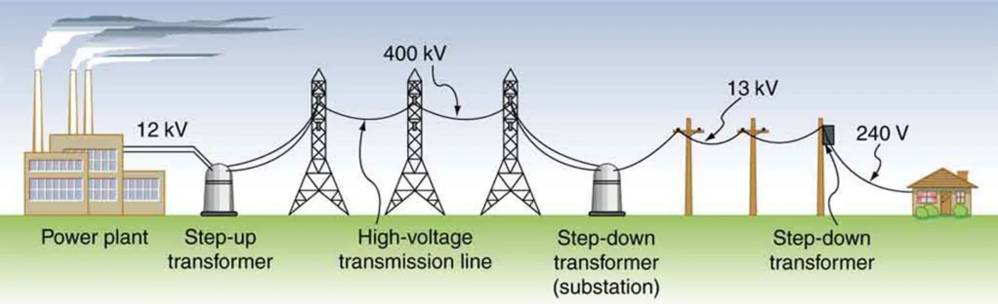
◀ Previous2 / 2
1How a transformer is built2How a transformer is built
How a transformer is built
1
The transformer studied here is based on Faraday’s law of induction and is built much like the apparatus Faraday used to show that a changing magnetic field can produce a current.
2
It has two coils, the primary coil and the secondary coil, wound on a shared iron core.
3
In normal use the input voltage is placed on the primary, and the secondary produces the transformed output voltage.
4
The iron core traps most of the magnetic field made by the primary, and its magnetization strengthens that field
so the flux reaches the secondary efficiently.
5
Because the input is AC, the flux changes continuously and induces an AC output in the secondary.
6
The core is laminated (built from thin insulated sheets) to reduce eddy currents,
which are circulating currents in the iron that waste energy as heat.
1 / 2Next ▶
Two coils wound on a laminated ferromagnetic core. The field from the primary is confined to the core and carried to the secondary, so a change in primary current induces a current in the secondary. Image: OpenStax, College Physics for AP Courses 2e, CC BY 4.0.
How a transformer is built

◀ Previous2 / 2
1Transformer equation2Transformer equation3Transformer equation
Transformer equation
Transformer equation
Faraday’s law gives the induced output voltage of the secondary as Vs = −Ns ΔΦ/Δt
where Vs is the secondary voltage in volts, Ns is the number of loops in the secondary coil, and ΔΦ/Δt is the rate of change of magnetic flux in webers per second (Wb/s). If the coil resistance is smallwhich is a reasonable assumption for transformers, the output voltage equals this induced emf.
The cross-sectional area and the field strength are the same on both sides of the core
so the same flux change ΔΦ/Δt passes through both coils.
The primary also has an induced emf.
Lenz’s law says the primary opposes the change caused by the input voltage
which gives the minus sign.
This is an example of self-inductance
which is explored in more detail later.
With negligible coil resistance, Kirchhoff’s loop rule says the induced emf exactly equals the input voltage,
so Vp = −Np ΔΦ/Δt,where Vp is the input voltage in volts and Np is the number of loops in the primary.
1 / 3Next ▶
Transformer equation
1
Dividing the two equations cancels the flux change and gives the transformer equation:
2
Vs / Vp = Ns / Np
3
What the symbols mean:
4
V = voltage (V) · N = number of turns · I = current (A) · p = primary coil · s = secondary coil
5
The ratio of the secondary voltage to the primary voltage equals the ratio of the number of loops in the two coils.
6
The output can be less than, greater than or equal to the input, depending on that ratio.
◀ Previous2 / 3Next ▶
Transformer equation
Transformer equation
A step-up transformer increases the voltage (Ns is greater than Np), and a step-down transformer decreases it (Ns is less than Np).
Some transformers allow connections at different points on the secondary coil
which gives a variable output.
◀ Previous3 / 3
Current and power in a transformer
Current and power in a transformer
If resistance is negligible, the electrical power output of a transformer equals its input: VpIp = VsIs
where I is current in amperes (A). Transformer efficiency often exceeds 99 percentso this equality is nearly true in practice. Efficiency is the output power divided by the input power, multiplied by 100 percent.
Rearranging this and combining it with the transformer equation gives Is / Ip = Vp / Vs = Np / Ns. So if the voltage increases, the current decreases, and if the voltage decreases, the current increases. The current ratio is the inverse of the voltage ratio.
1Why transformers need AC2Why transformers need AC
Why transformers need AC
1
Transformers cannot change a steady DC voltage.
2
Induction needs a changing magnetic flux.
3
If the primary voltage does not change, no voltage is induced in the secondary.
4
One possibility is to connect DC to the primary through a switch.
5
As the switch is opened and closed, the secondary produces voltage pulses
but this is not the sinusoidal AC most appliances need.
6
For that reason AC is used wherever voltages must be increased or decreased.
1 / 2Next ▶
When a DC input is switched on and off, the secondary produces brief voltage pulses rather than the smooth sine wave of AC. Image: OpenStax, College Physics for AP Courses 2e, CC BY 4.0.
Why transformers need AC

◀ Previous2 / 2
Battery chargers and rectifiers
Battery chargers and rectifiers
Some devices need DC even though the supply is AC.
A charger for ten nickel-cadmium cells (total emf 12.5 V DC) uses a step-down transformer to reduce the 120 V input to the 15.0 V needed for charging.
The output of the secondary is still AC
so it must be converted to DC.
This is done with a rectifier
which uses diodes, devices that allow current to flow in one direction only.
Transformers have many applications in electrical safety systems
which are covered in the lesson on electrical safety systems and devices.
Simulation: generator
Simulation: generator
The PhET simulation “Generator” lets you make electricity with a bar magnet and see how moving magnets can make a bulb light. Use it to explore how magnets and changing flux produce induced emf and current, the same principle behind the transformer and the motor.
1Back emf in a DC motor2Example 23.5: Step-up transformer for an x-ray unit3Example 23.5: Step-up transformer for an x-ray unit4Example 23.6: Step-down transformer for a battery charger5Example 23.6: Step-down transformer for a battery charger
Back emf in a DC motor
Back emf in a DC motor
Problem: A motor coil has a resistance of 0.400 Ω and is driven by a 48.0 V emf. Shortly after switching on, it draws a current and dissipates power as heat. At operating speed the back emf is 40.0 V. Find the starting current and power, and the operating current and power.
Starting: I = 48.0 V / 0.400 Ω = 120 A, and P = IV = 48.0 V × 120 A = 5.76 × 10³ W = 5.76 kW. This power would burn out the coils if sustained.
Operating: the net voltage across the coil is 48.0 V − 40.0 V = 8.0 V
so I = 8.0 V / 0.400 Ω = 20.0 A, and P = 8.0 V × 20.0 A = 160 W. This power is not a problem for the motor.
1 / 5Next ▶
Example 23.5: Step-up transformer for an x-ray unit
Example 23.5: Step-up transformer for an x-ray unit
Problem: A portable x-ray unit has a step-up transformer that changes a 120 V input into the 100 kV output needed by the x-ray tube. The primary has 50 loops and draws 10.00 A. Find (a) the number of loops in the secondary and (b) the secondary current.
(a) Solve Vs / Vp = Ns / Np for Ns: Ns = Np × Vs / Vp = 50 × (1.00 × 105 V) / (120 V) ≈ 4.17 × 10⁴ loops.
The secondary needs a very large number of loops compared with the primary to produce such a high voltage. This is typical of neon sign transformers and of the high-voltage supplies inside televisions and CRTs.
(b) Solve Is / Ip = Vp / Vs for Is: Is = Ip × Vp / Vs = 10.00 A × 120 V / (1.00 × 10⁵ V) = 1.20 × 10⁻² A = 12.0 mA.
The output current is much smaller than the input current.
Very large voltages can produce long arcs in demonstrations
but they are relatively safe because the transformer supplies only a small current.
◀ Previous2 / 5Next ▶
Example 23.5: Step-up transformer for an x-ray unit
Example 23.5: Step-up transformer for an x-ray unit
The input power, 120 V × 10.00 A = 1200 W, equals the output power, 1.00 × 105 V × 0.0120 A = 1200 W, as assumed in the derivation.
◀ Previous3 / 5Next ▶
Example 23.6: Step-down transformer for a battery charger
1
Problem: A battery charger for a 12.5 V DC battery pack needs a 15.0 V output. It uses a step-down transformer with a 200-loop primary and a 120 V input. Find (a) the number of loops in the secondary and (b) the input current when the charging current is 16.0 A.
2
(a) Ns = Np × Vs / Vp = 200 × 15.0 V / 120 V = 25 loops.
3
(b) Assuming 100 percent efficiency, Ip = Vs Is / Vp = 15.0 V × 16.0 A / 120 V = 2.0 A.
4
The secondary has a small number of loops, as expected for a step-down transformer, and a small input current produces a larger output current.
5
Power in is 120 V × 2.0 A = 240 W and power out is 15.0 V × 16.0 A = 240 W
which is consistent.
6
Transformers used to run large magnets sometimes have a few heavy secondary loops
giving low internal resistance and large current.
◀ Previous4 / 5Next ▶
Example 23.6: Step-down transformer for a battery charger
Example 23.6: Step-down transformer for a battery charger
Because the batteries need DC, the secondary output must also be rectified.
◀ Previous5 / 5
Key terms
| Term | Meaning |
|---|---|
| Back emf | The emf generated by a motor’s own turning coil, which opposes the driving voltage. |
| Transformer | A device that changes one AC voltage into another using electromagnetic induction. |
| Primary coil | The coil to which the input voltage is applied. |
| Secondary coil | The coil that delivers the transformed output voltage. |
| Iron core | A ferromagnetic core that traps and strengthens the magnetic field linking the two coils. |
| Eddy currents | Circulating currents induced in the core by a changing flux, which waste energy as heat. |
| Transformer equation | The relationship stating that the voltage ratio equals the ratio of the loop numbers in the two coils. |
| Step-up transformer | A transformer whose output voltage is greater than its input voltage. |
| Step-down transformer | A transformer whose output voltage is less than its input voltage. |
| Transformer efficiency | The output power divided by the input power, often above 99 percent for good transformers. |
| Rectifier | A circuit that converts AC into DC. |
| Diode | A device that allows current to flow in one direction only. |
| Self-inductance | The induced emf in a coil caused by a change in its own current. |
1Avoid these mistakes2Avoid these mistakes3Avoid these mistakes
Avoid these mistakes
1Avoid this
Inverting the transformer equation. The secondary-to-primary voltage ratio equals NAvoid this
sAvoid this
/ NAvoid this
pAvoid this
, not NAvoid this
1 / 3Next ▶
Avoid these mistakes
.Avoid this
2Avoid this
Thinking a transformer creates power. Ideally the power output equals the power input, so a voltage increase is always paired with a current decrease.Avoid this
3Avoid this
Applying a transformer to a steady DC voltage. A steady DC gives no changing flux, so no voltage is induced in the secondary.Avoid this
4Avoid this
◀ Previous2 / 3Next ▶
Avoid these mistakes
Using the driving emf instead of the net voltage in a motor. The voltage across the coil is the driving emf minus the back emf.Avoid this
5Avoid this
Assuming a step-up transformer adds energy. It raises the voltage and lowers the current for the same power.Avoid this
◀ Previous3 / 3