Curriculum
College Physics for AP Courses 2e
Unit 1: Introduction: The Nature of Science and Physics
0/10
-
Unit 1 overview: Introduction: The Nature of Science and Physics
 Text lessonPreview
-
1.1 Physics: An Introduction
Text lessonPreview
-
1.1 Physics: An Introduction - Check yourself
 6 questionsPreview
-
1.2 Physical Quantities and Units
Text lessonPreview
-
1.2 Physical Quantities and Units - Check yourself
6 questionsPreview
-
1.3 Accuracy, Precision, and Significant Figures
Text lessonPreview
-
1.3 Accuracy, Precision, and Significant Figures - Check yourself
6 questionsPreview
-
1.4 Approximation
Text lessonPreview
-
1.4 Approximation - Check yourself
6 questionsPreview
-
Unit 1 review quiz: Introduction: The Nature of Science and Physics
10 questionsPreview
Unit 2: Kinematics
0/18
-
Unit 2 overview: Kinematics
Text lessonPreview
-
2.1 Displacement
Text lessonPreview
-
2.1 Displacement - Check yourself
6 questionsPreview
-
2.2 Vectors, Scalars, and Coordinate Systems
Text lessonPreview
-
2.2 Vectors, Scalars, and Coordinate Systems - Check yourself
6 questionsPreview
-
2.3 Time, Velocity, and Speed
Text lessonPreview
-
2.3 Time, Velocity, and Speed - Check yourself
6 questionsPreview
-
2.4 Acceleration
Text lessonPreview
-
2.4 Acceleration - Check yourself
6 questionsPreview
-
2.5 Motion Equations for Constant Acceleration in One Dimension
Text lessonPreview
-
2.5 Motion Equations for Constant Acceleration in One Dimension - Check yourself
6 questionsPreview
-
2.6 Problem-Solving Basics for One-Dimensional Kinematics
Text lessonPreview
-
2.6 Problem-Solving Basics for One-Dimensional Kinematics - Check yourself
6 questionsPreview
-
2.7 Falling Objects
Text lessonPreview
-
2.7 Falling Objects - Check yourself
6 questionsPreview
-
2.8 Graphical Analysis of One-Dimensional Motion
Text lessonPreview
-
2.8 Graphical Analysis of One-Dimensional Motion - Check yourself
6 questionsPreview
-
Unit 2 review quiz: Kinematics
10 questionsPreview
Unit 3: Two-Dimensional Kinematics
0/12
-
Unit 3 overview: Two-Dimensional Kinematics
Text lessonPreview
-
3.1 Kinematics in Two Dimensions: An Introduction
Text lessonPreview
-
3.1 Kinematics in Two Dimensions: An Introduction - Check yourself
6 questionsPreview
-
3.2 Vector Addition and Subtraction: Graphical Methods
Text lessonPreview
-
3.2 Vector Addition and Subtraction: Graphical Methods - Check yourself
6 questionsPreview
-
3.3 Vector Addition and Subtraction: Analytical Methods
Text lessonPreview
-
3.3 Vector Addition and Subtraction: Analytical Methods - Check yourself
6 questionsPreview
-
3.4 Projectile Motion
Text lessonPreview
-
3.4 Projectile Motion - Check yourself
6 questionsPreview
-
3.5 Addition of Velocities
Text lessonPreview
-
3.5 Addition of Velocities - Check yourself
6 questionsPreview
-
Unit 3 review quiz: Two-Dimensional Kinematics
10 questionsPreview
Unit 4: Dynamics: Force and Newton's Laws of Motion
0/18
-
Unit 4 overview: Dynamics: Force and Newton's Laws of Motion
Text lessonPreview
-
4.1 Development of Force Concept
Text lessonPreview
-
4.1 Development of Force Concept - Check yourself
6 questionsPreview
-
4.2 Newton’s First Law of Motion: Inertia
Text lessonPreview
-
4.2 Newton’s First Law of Motion: Inertia - Check yourself
6 questionsPreview
-
4.3 Newton’s Second Law of Motion: Concept of a System
Text lessonPreview
-
4.3 Newton’s Second Law of Motion: Concept of a System - Check yourself
6 questionsPreview
-
4.4 Newton’s Third Law of Motion: Symmetry in Forces
Text lessonPreview
-
4.4 Newton’s Third Law of Motion: Symmetry in Forces - Check yourself
6 questionsPreview
-
4.5 Normal, Tension, and Other Examples of Forces
Text lessonPreview
-
4.5 Normal, Tension, and Other Examples of Forces - Check yourself
6 questionsPreview
-
4.6 Problem-Solving Strategies
Text lessonPreview
-
4.6 Problem-Solving Strategies - Check yourself
6 questionsPreview
-
4.7 Further Applications of Newton’s Laws of Motion
Text lessonPreview
-
4.7 Further Applications of Newton’s Laws of Motion - Check yourself
6 questionsPreview
-
4.8 Extended Topic: The Four Basic Forces—An Introduction
Text lessonPreview
-
4.8 Extended Topic: The Four Basic Forces—An Introduction - Check yourself
6 questionsPreview
-
Unit 4 review quiz: Dynamics: Force and Newton's Laws of Motion
10 questionsPreview
Unit 5: Further Applications of Newton's Laws: Friction, Drag, and Elasticity
0/8
-
Unit 5 overview: Further Applications of Newton's Laws: Friction, Drag, and Elasticity
Text lessonPreview
-
5.1 Friction
Text lessonPreview
-
5.1 Friction - Check yourself
6 questionsPreview
-
5.2 Drag Forces
Text lessonPreview
-
5.2 Drag Forces - Check yourself
6 questionsPreview
-
5.3 Elasticity: Stress and Strain
Text lessonPreview
-
5.3 Elasticity: Stress and Strain - Check yourself
6 questionsPreview
-
Unit 5 review quiz: Further Applications of Newton's Laws: Friction, Drag, and Elasticity
10 questionsPreview
Unit 6: Uniform Circular Motion and Gravitation
0/14
-
Unit 6 overview: Uniform Circular Motion and Gravitation
Text lessonPreview
-
6.1 Rotation Angle and Angular Velocity
Text lessonPreview
-
6.1 Rotation Angle and Angular Velocity - Check yourself
6 questionsPreview
-
6.2 Centripetal Acceleration
Text lessonPreview
-
6.2 Centripetal Acceleration - Check yourself
6 questionsPreview
-
6.3 Centripetal Force
Text lessonPreview
-
6.3 Centripetal Force - Check yourself
6 questionsPreview
-
6.4 Fictitious Forces and Non-inertial Frames: The Coriolis Force
Text lessonPreview
-
6.4 Fictitious Forces and Non-inertial Frames: The Coriolis Force - Check yourself
6 questionsPreview
-
6.5 Newton’s Universal Law of Gravitation
Text lessonPreview
-
6.5 Newton’s Universal Law of Gravitation - Check yourself
6 questionsPreview
-
6.6 Satellites and Kepler’s Laws: An Argument for Simplicity
Text lessonPreview
-
6.6 Satellites and Kepler’s Laws: An Argument for Simplicity - Check yourself
6 questionsPreview
-
Unit 6 review quiz: Uniform Circular Motion and Gravitation
10 questionsPreview
Unit 7: Work, Energy, and Energy Resources
0/20
-
Unit 7 overview: Work, Energy, and Energy Resources
Text lessonPreview
-
7.1 Work: The Scientific Definition
Text lessonPreview
-
7.1 Work: The Scientific Definition - Check yourself
6 questionsPreview
-
7.2 Kinetic Energy and the Work-Energy Theorem
Text lessonPreview
-
7.2 Kinetic Energy and the Work-Energy Theorem - Check yourself
6 questionsPreview
-
7.3 Gravitational Potential Energy
Text lessonPreview
-
7.3 Gravitational Potential Energy - Check yourself
6 questionsPreview
-
7.4 Conservative Forces and Potential Energy
Text lessonPreview
-
7.4 Conservative Forces and Potential Energy - Check yourself
6 questionsPreview
-
7.5 Nonconservative Forces
Text lessonPreview
-
7.5 Nonconservative Forces - Check yourself
6 questionsPreview
-
7.6 Conservation of Energy
Text lessonPreview
-
7.6 Conservation of Energy - Check yourself
6 questionsPreview
-
7.7 Power
Text lessonPreview
-
7.7 Power - Check yourself
6 questionsPreview
-
7.8 Work, Energy, and Power in Humans
Text lessonPreview
-
7.8 Work, Energy, and Power in Humans - Check yourself
6 questionsPreview
-
7.9 World Energy Use
Text lessonPreview
-
7.9 World Energy Use - Check yourself
6 questionsPreview
-
Unit 7 review quiz: Work, Energy, and Energy Resources
10 questionsPreview
Unit 8: Linear Momentum and Collisions
0/32
-
Unit 8 overview: Linear Momentum and Collisions
Text lessonPreview
-
8.1 Linear Momentum and Force
Text lessonPreview
-
8.1 Linear Momentum and Force - Check yourself
6 questionsPreview
-
8.1 Linear Momentum and Force
Text lessonPreview
-
8.1 Linear Momentum and Force - Check yourself
6 questionsPreview
-
8.2 Impulse
Text lessonPreview
-
8.2 Impulse - Check yourself
6 questionsPreview
-
8.2 Impulse
Text lessonPreview
-
8.2 Impulse - Check yourself
6 questionsPreview
-
8.3 Conservation of Momentum
Text lessonPreview
-
8.3 Conservation of Momentum - Check yourself
6 questionsPreview
-
8.3 Conservation of Momentum
Text lessonPreview
-
8.3 Conservation of Momentum - Check yourself
6 questionsPreview
-
8.4 Elastic Collisions in One Dimension
Text lessonPreview
-
8.4 Elastic Collisions in One Dimension - Check yourself
6 questionsPreview
-
Unit 8 review quiz: Linear Momentum and Collisions
10 questionsPreview
-
Unit 8 overview: Linear Momentum and Collisions
Text lessonPreview
-
8.4 Elastic Collisions in One Dimension
Text lessonPreview
-
8.4 Elastic Collisions in One Dimension - Check yourself
6 questionsPreview
-
8.5 Inelastic Collisions in One Dimension
Text lessonPreview
-
8.5 Inelastic Collisions in One Dimension - Check yourself
6 questionsPreview
-
8.5 Inelastic Collisions in One Dimension
Text lessonPreview
-
8.5 Inelastic Collisions in One Dimension - Check yourself
6 questionsPreview
-
8.6 Collisions of Point Masses in Two Dimensions
Text lessonPreview
-
8.6 Collisions of Point Masses in Two Dimensions - Check yourself
6 questionsPreview
-
8.6 Collisions of Point Masses in Two Dimensions
Text lessonPreview
-
8.6 Collisions of Point Masses in Two Dimensions - Check yourself
6 questionsPreview
-
8.7 Introduction to Rocket Propulsion
Text lessonPreview
-
8.7 Introduction to Rocket Propulsion - Check yourself
6 questionsPreview
-
8.7 Introduction to Rocket Propulsion
Text lessonPreview
-
8.7 Introduction to Rocket Propulsion - Check yourself
6 questionsPreview
-
Unit 8 review quiz: Linear Momentum and Collisions
10 questionsPreview
Unit 9: Statics and Torque
0/28
-
Unit 9 overview: Statics and Torque
Text lessonPreview
-
9.1 The First Condition for Equilibrium
Text lessonPreview
-
9.1 The First Condition for Equilibrium - Check yourself
6 questionsPreview
-
9.1 The First Condition for Equilibrium
Text lessonPreview
-
9.1 The First Condition for Equilibrium - Check yourself
6 questionsPreview
-
9.2 The Second Condition for Equilibrium
Text lessonPreview
-
9.2 The Second Condition for Equilibrium - Check yourself
6 questionsPreview
-
9.2 The Second Condition for Equilibrium
Text lessonPreview
-
9.2 The Second Condition for Equilibrium - Check yourself
6 questionsPreview
-
9.3 Stability
Text lessonPreview
-
9.3 Stability - Check yourself
6 questionsPreview
-
9.3 Stability
Text lessonPreview
-
9.3 Stability - Check yourself
6 questionsPreview
-
Unit 9 review quiz: Statics and Torque
10 questionsPreview
-
Unit 9 overview: Statics and Torque
Text lessonPreview
-
9.4 Applications of Statics, Including Problem-Solving Strategies
Text lessonPreview
-
9.4 Applications of Statics, Including Problem-Solving Strategies - Check yourself
6 questionsPreview
-
9.4 Applications of Statics, Including Problem-Solving Strategies
Text lessonPreview
-
9.4 Applications of Statics, Including Problem-Solving Strategies - Check yourself
6 questionsPreview
-
9.5 Simple Machines
Text lessonPreview
-
9.5 Simple Machines - Check yourself
6 questionsPreview
-
9.5 Simple Machines
Text lessonPreview
-
9.5 Simple Machines - Check yourself
6 questionsPreview
-
9.6 Forces and Torques in Muscles and Joints
Text lessonPreview
-
9.6 Forces and Torques in Muscles and Joints - Check yourself
6 questionsPreview
-
9.6 Forces and Torques in Muscles and Joints
Text lessonPreview
-
9.6 Forces and Torques in Muscles and Joints - Check yourself
6 questionsPreview
-
Unit 9 review quiz: Statics and Torque
10 questionsPreview
Unit 10: Rotational Motion and Angular Momentum
0/32
-
Unit 10 overview: Rotational Motion and Angular Momentum
Text lessonPreview
-
10.1 Angular Acceleration
Text lessonPreview
-
10.1 Angular Acceleration - Check yourself
6 questionsPreview
-
10.1 Angular Acceleration
Text lessonPreview
-
10.1 Angular Acceleration - Check yourself
6 questionsPreview
-
10.2 Kinematics of Rotational Motion
Text lessonPreview
-
10.2 Kinematics of Rotational Motion - Check yourself
6 questionsPreview
-
10.2 Kinematics of Rotational Motion
Text lessonPreview
-
10.2 Kinematics of Rotational Motion - Check yourself
6 questionsPreview
-
10.3 Dynamics of Rotational Motion: Rotational Inertia
Text lessonPreview
-
10.3 Dynamics of Rotational Motion: Rotational Inertia - Check yourself
6 questionsPreview
-
10.3 Dynamics of Rotational Motion: Rotational Inertia
Text lessonPreview
-
10.3 Dynamics of Rotational Motion: Rotational Inertia - Check yourself
6 questionsPreview
-
10.4 Rotational Kinetic Energy: Work and Energy Revisited
Text lessonPreview
-
10.4 Rotational Kinetic Energy: Work and Energy Revisited - Check yourself
6 questionsPreview
-
Unit 10 review quiz: Rotational Motion and Angular Momentum
10 questionsPreview
-
Unit 10 overview: Rotational Motion and Angular Momentum
Text lessonPreview
-
10.4 Rotational Kinetic Energy: Work and Energy Revisited
Text lessonPreview
-
10.4 Rotational Kinetic Energy: Work and Energy Revisited - Check yourself
6 questionsPreview
-
10.5 Angular Momentum and Its Conservation
Text lessonPreview
-
10.5 Angular Momentum and Its Conservation - Check yourself
6 questionsPreview
-
10.5 Angular Momentum and Its Conservation
Text lessonPreview
-
10.5 Angular Momentum and Its Conservation - Check yourself
6 questionsPreview
-
10.6 Collisions of Extended Bodies in Two Dimensions
Text lessonPreview
-
10.6 Collisions of Extended Bodies in Two Dimensions - Check yourself
6 questionsPreview
-
10.6 Collisions of Extended Bodies in Two Dimensions
Text lessonPreview
-
10.6 Collisions of Extended Bodies in Two Dimensions - Check yourself
6 questionsPreview
-
10.7 Gyroscopic Effects: Vector Aspects of Angular Momentum
Text lessonPreview
-
10.7 Gyroscopic Effects: Vector Aspects of Angular Momentum - Check yourself
6 questionsPreview
-
10.7 Gyroscopic Effects: Vector Aspects of Angular Momentum
Text lessonPreview
-
10.7 Gyroscopic Effects: Vector Aspects of Angular Momentum - Check yourself
6 questionsPreview
-
Unit 10 review quiz: Rotational Motion and Angular Momentum
10 questionsPreview
Unit 11: Fluid Statics
0/40
-
Unit 11 overview: Fluid Statics
Text lessonPreview
-
11.1 What Is a Fluid?
Text lessonPreview
-
11.1 What Is a Fluid? - Check yourself
6 questionsPreview
-
11.1 What Is a Fluid?
Text lessonPreview
-
11.1 What Is a Fluid? - Check yourself
6 questionsPreview
-
11.2 Density
Text lessonPreview
-
11.2 Density - Check yourself
6 questionsPreview
-
11.2 Density
Text lessonPreview
-
11.2 Density - Check yourself
6 questionsPreview
-
11.3 Pressure
Text lessonPreview
-
11.3 Pressure - Check yourself
6 questionsPreview
-
11.3 Pressure
Text lessonPreview
-
11.3 Pressure - Check yourself
6 questionsPreview
-
11.4 Variation of Pressure with Depth in a Fluid
Text lessonPreview
-
11.4 Variation of Pressure with Depth in a Fluid - Check yourself
6 questionsPreview
-
11.4 Variation of Pressure with Depth in a Fluid
Text lessonPreview
-
11.4 Variation of Pressure with Depth in a Fluid - Check yourself
6 questionsPreview
-
11.5 Pascal’s Principle
Text lessonPreview
-
11.5 Pascal’s Principle - Check yourself
6 questionsPreview
-
Unit 11 review quiz: Fluid Statics
10 questionsPreview
-
Unit 11 overview: Fluid Statics
Text lessonPreview
-
11.5 Pascal’s Principle
Text lessonPreview
-
11.5 Pascal’s Principle - Check yourself
6 questionsPreview
-
11.6 Gauge Pressure, Absolute Pressure, and Pressure Measurement
Text lessonPreview
-
11.6 Gauge Pressure, Absolute Pressure, and Pressure Measurement - Check yourself
6 questionsPreview
-
11.6 Gauge Pressure, Absolute Pressure, and Pressure Measurement
Text lessonPreview
-
11.6 Gauge Pressure, Absolute Pressure, and Pressure Measurement - Check yourself
6 questionsPreview
-
11.7 Archimedes’ Principle
Text lessonPreview
-
11.7 Archimedes’ Principle - Check yourself
6 questionsPreview
-
11.7 Archimedes’ Principle
Text lessonPreview
-
11.7 Archimedes’ Principle - Check yourself
6 questionsPreview
-
11.8 Cohesion and Adhesion in Liquids: Surface Tension and Capillary Action
Text lessonPreview
-
11.8 Cohesion and Adhesion in Liquids: Surface Tension and Capillary Action - Check yourself
6 questionsPreview
-
11.8 Cohesion and Adhesion in Liquids: Surface Tension and Capillary Action
Text lessonPreview
-
11.8 Cohesion and Adhesion in Liquids: Surface Tension and Capillary Action - Check yourself
6 questionsPreview
-
11.9 Pressures in the Body
Text lessonPreview
-
11.9 Pressures in the Body - Check yourself
6 questionsPreview
-
11.9 Pressures in the Body
Text lessonPreview
-
11.9 Pressures in the Body - Check yourself
6 questionsPreview
-
Unit 11 review quiz: Fluid Statics
10 questionsPreview
Unit 12: Fluid Dynamics and Its Biological and Medical Applications
0/32
-
Unit 12 overview: Fluid Dynamics and Its Biological and Medical Applications
Text lessonPreview
-
12.1 Flow Rate and Its Relation to Velocity
Text lessonPreview
-
12.1 Flow Rate and Its Relation to Velocity - Check yourself
6 questionsPreview
-
12.1 Flow Rate and Its Relation to Velocity
Text lessonPreview
-
12.1 Flow Rate and Its Relation to Velocity - Check yourself
6 questionsPreview
-
12.2 Bernoulli’s Equation
Text lessonPreview
-
12.2 Bernoulli’s Equation - Check yourself
6 questionsPreview
-
12.2 Bernoulli’s Equation
Text lessonPreview
-
12.2 Bernoulli’s Equation - Check yourself
6 questionsPreview
-
12.3 The Most General Applications of Bernoulli’s Equation
Text lessonPreview
-
12.3 The Most General Applications of Bernoulli’s Equation - Check yourself
6 questionsPreview
-
12.3 The Most General Applications of Bernoulli’s Equation
Text lessonPreview
-
12.3 The Most General Applications of Bernoulli’s Equation - Check yourself
6 questionsPreview
-
12.4 Viscosity and Laminar Flow; Poiseuille’s Law
Text lessonPreview
-
12.4 Viscosity and Laminar Flow; Poiseuille’s Law - Check yourself
6 questionsPreview
-
Unit 12 review quiz: Fluid Dynamics and Its Biological and Medical Applications
10 questionsPreview
-
Unit 12 overview: Fluid Dynamics and Its Biological and Medical Applications
Text lessonPreview
-
12.4 Viscosity and Laminar Flow; Poiseuille’s Law
Text lessonPreview
-
12.4 Viscosity and Laminar Flow; Poiseuille’s Law - Check yourself
6 questionsPreview
-
12.5 The Onset of Turbulence
Text lessonPreview
-
12.5 The Onset of Turbulence - Check yourself
6 questionsPreview
-
12.5 The Onset of Turbulence
Text lessonPreview
-
12.5 The Onset of Turbulence - Check yourself
6 questionsPreview
-
12.6 Motion of an Object in a Viscous Fluid
Text lessonPreview
-
12.6 Motion of an Object in a Viscous Fluid - Check yourself
6 questionsPreview
-
12.6 Motion of an Object in a Viscous Fluid
Text lessonPreview
-
12.6 Motion of an Object in a Viscous Fluid - Check yourself
6 questionsPreview
-
12.7 Molecular Transport Phenomena: Diffusion, Osmosis, and Related Processes
Text lessonPreview
-
12.7 Molecular Transport Phenomena: Diffusion, Osmosis, and Related Processes - Check yourself
6 questionsPreview
-
12.7 Molecular Transport Phenomena: Diffusion, Osmosis, and Related Processes
Text lessonPreview
-
12.7 Molecular Transport Phenomena: Diffusion, Osmosis, and Related Processes - Check yourself
6 questionsPreview
-
Unit 12 review quiz: Fluid Dynamics and Its Biological and Medical Applications
10 questionsPreview
Unit 13: Temperature, Kinetic Theory, and the Gas Laws
0/28
-
Unit 13 overview: Temperature, Kinetic Theory, and the Gas Laws
Text lessonPreview
-
13.1 Temperature
Text lessonPreview
-
13.1 Temperature - Check yourself
6 questionsPreview
-
13.1 Temperature
Text lessonPreview
-
13.1 Temperature - Check yourself
6 questionsPreview
-
13.2 Thermal Expansion of Solids and Liquids
Text lessonPreview
-
13.2 Thermal Expansion of Solids and Liquids - Check yourself
6 questionsPreview
-
13.2 Thermal Expansion of Solids and Liquids
Text lessonPreview
-
13.2 Thermal Expansion of Solids and Liquids - Check yourself
6 questionsPreview
-
13.3 The Ideal Gas Law
Text lessonPreview
-
13.3 The Ideal Gas Law - Check yourself
6 questionsPreview
-
13.3 The Ideal Gas Law
Text lessonPreview
-
13.3 The Ideal Gas Law - Check yourself
6 questionsPreview
-
Unit 13 review quiz: Temperature, Kinetic Theory, and the Gas Laws
10 questionsPreview
-
Unit 13 overview: Temperature, Kinetic Theory, and the Gas Laws
Text lessonPreview
-
13.4 Kinetic Theory: Atomic and Molecular Explanation of Pressure and Temperature
Text lessonPreview
-
13.4 Kinetic Theory: Atomic and Molecular Explanation of Pressure and Temperature - Check yourself
6 questionsPreview
-
13.4 Kinetic Theory: Atomic and Molecular Explanation of Pressure and Temperature
Text lessonPreview
-
13.4 Kinetic Theory: Atomic and Molecular Explanation of Pressure and Temperature - Check yourself
6 questionsPreview
-
13.5 Phase Changes
Text lessonPreview
-
13.5 Phase Changes - Check yourself
6 questionsPreview
-
13.5 Phase Changes
Text lessonPreview
-
13.5 Phase Changes - Check yourself
6 questionsPreview
-
13.6 Humidity, Evaporation, and Boiling
Text lessonPreview
-
13.6 Humidity, Evaporation, and Boiling - Check yourself
6 questionsPreview
-
13.6 Humidity, Evaporation, and Boiling
Text lessonPreview
-
13.6 Humidity, Evaporation, and Boiling - Check yourself
6 questionsPreview
-
Unit 13 review quiz: Temperature, Kinetic Theory, and the Gas Laws
10 questionsPreview
Unit 14: Heat and Heat Transfer Methods
0/32
-
Unit 14 overview: Heat and Heat Transfer Methods
Text lessonPreview
-
14.1 Heat
Text lessonPreview
-
14.1 Heat - Check yourself
6 questionsPreview
-
14.1 Heat
Text lessonPreview
-
14.1 Heat - Check yourself
6 questionsPreview
-
14.2 Temperature Change and Heat Capacity
Text lessonPreview
-
14.2 Temperature Change and Heat Capacity - Check yourself
6 questionsPreview
-
14.2 Temperature Change and Heat Capacity
Text lessonPreview
-
14.2 Temperature Change and Heat Capacity - Check yourself
6 questionsPreview
-
14.3 Phase Change and Latent Heat
Text lessonPreview
-
14.3 Phase Change and Latent Heat - Check yourself
6 questionsPreview
-
14.3 Phase Change and Latent Heat
Text lessonPreview
-
14.3 Phase Change and Latent Heat - Check yourself
6 questionsPreview
-
14.4 Heat Transfer Methods
Text lessonPreview
-
14.4 Heat Transfer Methods - Check yourself
6 questionsPreview
-
Unit 14 review quiz: Heat and Heat Transfer Methods
10 questionsPreview
-
Unit 14 overview: Heat and Heat Transfer Methods
Text lessonPreview
-
14.4 Heat Transfer Methods
Text lessonPreview
-
14.4 Heat Transfer Methods - Check yourself
6 questionsPreview
-
14.5 Conduction
Text lessonPreview
-
14.5 Conduction - Check yourself
6 questionsPreview
-
14.5 Conduction
Text lessonPreview
-
14.5 Conduction - Check yourself
6 questionsPreview
-
14.6 Convection
Text lessonPreview
-
14.6 Convection - Check yourself
6 questionsPreview
-
14.6 Convection
Text lessonPreview
-
14.6 Convection - Check yourself
6 questionsPreview
-
14.7 Radiation
Text lessonPreview
-
14.7 Radiation - Check yourself
6 questionsPreview
-
14.7 Radiation
Text lessonPreview
-
14.7 Radiation - Check yourself
6 questionsPreview
-
Unit 14 review quiz: Heat and Heat Transfer Methods
10 questionsPreview
Unit 15: Thermodynamics
0/32
-
Unit 15 overview: Thermodynamics
Text lessonPreview
-
15.1 The First Law of Thermodynamics
Text lessonPreview
-
15.1 The First Law of Thermodynamics - Check yourself
6 questionsPreview
-
15.1 The First Law of Thermodynamics
Text lessonPreview
-
15.1 The First Law of Thermodynamics - Check yourself
6 questionsPreview
-
15.2 The First Law of Thermodynamics and Some Simple Processes
Text lessonPreview
-
15.2 The First Law of Thermodynamics and Some Simple Processes - Check yourself
6 questionsPreview
-
15.2 The First Law of Thermodynamics and Some Simple Processes
Text lessonPreview
-
15.2 The First Law of Thermodynamics and Some Simple Processes - Check yourself
6 questionsPreview
-
15.3 Introduction to the Second Law of Thermodynamics: Heat Engines and Their Efficiency
Text lessonPreview
-
15.3 Introduction to the Second Law of Thermodynamics: Heat Engines and Their Efficiency - Check yourself
6 questionsPreview
-
15.3 Introduction to the Second Law of Thermodynamics: Heat Engines and Their Efficiency
Text lessonPreview
-
15.3 Introduction to the Second Law of Thermodynamics: Heat Engines and Their Efficiency - Check yourself
6 questionsPreview
-
15.4 Carnot’s Perfect Heat Engine: The Second Law of Thermodynamics Restated
Text lessonPreview
-
15.4 Carnot’s Perfect Heat Engine: The Second Law of Thermodynamics Restated - Check yourself
6 questionsPreview
-
Unit 15 review quiz: Thermodynamics
10 questionsPreview
-
Unit 15 overview: Thermodynamics
Text lessonPreview
-
15.4 Carnot’s Perfect Heat Engine: The Second Law of Thermodynamics Restated
Text lessonPreview
-
15.4 Carnot’s Perfect Heat Engine: The Second Law of Thermodynamics Restated - Check yourself
6 questionsPreview
-
15.5 Applications of Thermodynamics: Heat Pumps and Refrigerators
Text lessonPreview
-
15.5 Applications of Thermodynamics: Heat Pumps and Refrigerators - Check yourself
6 questionsPreview
-
15.5 Applications of Thermodynamics: Heat Pumps and Refrigerators
Text lessonPreview
-
15.5 Applications of Thermodynamics: Heat Pumps and Refrigerators - Check yourself
6 questionsPreview
-
15.6 Entropy and the Second Law of Thermodynamics: Disorder and the Unavailability of Energy
Text lessonPreview
-
15.6 Entropy and the Second Law of Thermodynamics: Disorder and the Unavailability of Energy - Check yourself
6 questionsPreview
-
15.6 Entropy and the Second Law of Thermodynamics: Disorder and the Unavailability of Energy
Text lessonPreview
-
15.6 Entropy and the Second Law of Thermodynamics: Disorder and the Unavailability of Energy - Check yourself
6 questionsPreview
-
15.7 Statistical Interpretation of Entropy and the Second Law of Thermodynamics: The Underlying Explanation
Text lessonPreview
-
15.7 Statistical Interpretation of Entropy and the Second Law of Thermodynamics: The Underlying Explanation - Check yourself
6 questionsPreview
-
15.7 Statistical Interpretation of Entropy and the Second Law of Thermodynamics: The Underlying Explanation
Text lessonPreview
-
15.7 Statistical Interpretation of Entropy and the Second Law of Thermodynamics: The Underlying Explanation - Check yourself
6 questionsPreview
-
Unit 15 review quiz: Thermodynamics
10 questionsPreview
Unit 16: Oscillatory Motion and Waves
0/48
-
Unit 16 overview: Oscillatory Motion and Waves
Text lessonPreview
-
16.1 Hooke’s Law: Stress and Strain Revisited
Text lessonPreview
-
16.1 Hooke’s Law: Stress and Strain Revisited - Check yourself
6 questionsPreview
-
16.1 Hooke’s Law: Stress and Strain Revisited
Text lessonPreview
-
16.1 Hooke’s Law: Stress and Strain Revisited - Check yourself
6 questionsPreview
-
16.2 Period and Frequency in Oscillations
Text lessonPreview
-
16.2 Period and Frequency in Oscillations - Check yourself
6 questionsPreview
-
16.2 Period and Frequency in Oscillations
Text lessonPreview
-
16.2 Period and Frequency in Oscillations - Check yourself
6 questionsPreview
-
16.3 Simple Harmonic Motion: A Special Periodic Motion
Text lessonPreview
-
16.3 Simple Harmonic Motion: A Special Periodic Motion - Check yourself
6 questionsPreview
-
16.3 Simple Harmonic Motion: A Special Periodic Motion
Text lessonPreview
-
16.3 Simple Harmonic Motion: A Special Periodic Motion - Check yourself
6 questionsPreview
-
16.4 The Simple Pendulum
Text lessonPreview
-
16.4 The Simple Pendulum - Check yourself
6 questionsPreview
-
16.4 The Simple Pendulum
Text lessonPreview
-
16.4 The Simple Pendulum - Check yourself
6 questionsPreview
-
16.5 Energy and the Simple Harmonic Oscillator
Text lessonPreview
-
16.5 Energy and the Simple Harmonic Oscillator - Check yourself
6 questionsPreview
-
16.5 Energy and the Simple Harmonic Oscillator
Text lessonPreview
-
16.5 Energy and the Simple Harmonic Oscillator - Check yourself
6 questionsPreview
-
16.6 Uniform Circular Motion and Simple Harmonic Motion
Text lessonPreview
-
16.6 Uniform Circular Motion and Simple Harmonic Motion - Check yourself
6 questionsPreview
-
Unit 16 review quiz: Oscillatory Motion and Waves
10 questionsPreview
-
Unit 16 overview: Oscillatory Motion and Waves
Text lessonPreview
-
16.6 Uniform Circular Motion and Simple Harmonic Motion
Text lessonPreview
-
16.6 Uniform Circular Motion and Simple Harmonic Motion - Check yourself
6 questionsPreview
-
16.7 Damped Harmonic Motion
Text lessonPreview
-
16.7 Damped Harmonic Motion - Check yourself
6 questionsPreview
-
16.7 Damped Harmonic Motion
Text lessonPreview
-
16.7 Damped Harmonic Motion - Check yourself
6 questionsPreview
-
16.8 Forced Oscillations and Resonance
Text lessonPreview
-
16.8 Forced Oscillations and Resonance - Check yourself
6 questionsPreview
-
16.8 Forced Oscillations and Resonance
Text lessonPreview
-
16.8 Forced Oscillations and Resonance - Check yourself
6 questionsPreview
-
16.9 Waves
Text lessonPreview
-
16.9 Waves - Check yourself
6 questionsPreview
-
16.9 Waves
Text lessonPreview
-
16.9 Waves - Check yourself
6 questionsPreview
-
16.10 Superposition and Interference
Text lessonPreview
-
16.10 Superposition and Interference - Check yourself
6 questionsPreview
-
16.10 Superposition and Interference
Text lessonPreview
-
16.10 Superposition and Interference - Check yourself
6 questionsPreview
-
16.11 Energy in Waves: Intensity
Text lessonPreview
-
16.11 Energy in Waves: Intensity - Check yourself
6 questionsPreview
-
16.11 Energy in Waves: Intensity
Text lessonPreview
-
16.11 Energy in Waves: Intensity - Check yourself
6 questionsPreview
-
Unit 16 review quiz: Oscillatory Motion and Waves
10 questionsPreview
Unit 17: Physics of Hearing
0/32
-
Unit 17 overview: Physics of Hearing
Text lessonPreview
-
17.1 Sound
Text lessonPreview
-
17.1 Sound - Check yourself
6 questionsPreview
-
17.1 Sound
Text lessonPreview
-
17.1 Sound - Check yourself
6 questionsPreview
-
17.2 Speed of Sound, Frequency, and Wavelength
Text lessonPreview
-
17.2 Speed of Sound, Frequency, and Wavelength - Check yourself
6 questionsPreview
-
17.2 Speed of Sound, Frequency, and Wavelength
Text lessonPreview
-
17.2 Speed of Sound, Frequency, and Wavelength - Check yourself
6 questionsPreview
-
17.3 Sound Intensity and Sound Level
Text lessonPreview
-
17.3 Sound Intensity and Sound Level - Check yourself
6 questionsPreview
-
17.3 Sound Intensity and Sound Level
Text lessonPreview
-
17.3 Sound Intensity and Sound Level - Check yourself
6 questionsPreview
-
17.4 Doppler Effect and Sonic Booms
Text lessonPreview
-
17.4 Doppler Effect and Sonic Booms - Check yourself
6 questionsPreview
-
Unit 17 review quiz: Physics of Hearing
10 questionsPreview
-
Unit 17 overview: Physics of Hearing
Text lessonPreview
-
17.4 Doppler Effect and Sonic Booms
Text lessonPreview
-
17.4 Doppler Effect and Sonic Booms - Check yourself
6 questionsPreview
-
17.5 Sound Interference and Resonance: Standing Waves in Air Columns
Text lessonPreview
-
17.5 Sound Interference and Resonance: Standing Waves in Air Columns - Check yourself
6 questionsPreview
-
17.5 Sound Interference and Resonance: Standing Waves in Air Columns
Text lessonPreview
-
17.5 Sound Interference and Resonance: Standing Waves in Air Columns - Check yourself
6 questionsPreview
-
17.6 Hearing
Text lessonPreview
-
17.6 Hearing - Check yourself
6 questionsPreview
-
17.6 Hearing
Text lessonPreview
-
17.6 Hearing - Check yourself
6 questionsPreview
-
17.7 Ultrasound
Text lessonPreview
-
17.7 Ultrasound - Check yourself
6 questionsPreview
-
17.7 Ultrasound
Text lessonPreview
-
17.7 Ultrasound - Check yourself
6 questionsPreview
-
Unit 17 review quiz: Physics of Hearing
10 questionsPreview
Unit 18: Electric Charge and Electric Field
0/36
-
Unit 18 overview: Electric Charge and Electric Field
Text lessonPreview
-
18.1 Static Electricity and Charge: Conservation of Charge
Text lessonPreview
-
18.1 Static Electricity and Charge: Conservation of Charge - Check yourself
6 questionsPreview
-
18.1 Static Electricity and Charge: Conservation of Charge
Text lessonPreview
-
18.1 Static Electricity and Charge: Conservation of Charge - Check yourself
6 questionsPreview
-
18.2 Conductors and Insulators
Text lessonPreview
-
18.2 Conductors and Insulators - Check yourself
6 questionsPreview
-
18.2 Conductors and Insulators
Text lessonPreview
-
18.2 Conductors and Insulators - Check yourself
6 questionsPreview
-
18.3 Conductors and Electric Fields in Static Equilibrium
Text lessonPreview
-
18.3 Conductors and Electric Fields in Static Equilibrium - Check yourself
6 questionsPreview
-
18.3 Conductors and Electric Fields in Static Equilibrium
Text lessonPreview
-
18.3 Conductors and Electric Fields in Static Equilibrium - Check yourself
6 questionsPreview
-
18.4 Coulomb’s Law
Text lessonPreview
-
18.4 Coulomb’s Law - Check yourself
6 questionsPreview
-
18.4 Coulomb’s Law
Text lessonPreview
-
18.4 Coulomb’s Law - Check yourself
6 questionsPreview
-
Unit 18 review quiz: Electric Charge and Electric Field
10 questionsPreview
-
Unit 18 overview: Electric Charge and Electric Field
Text lessonPreview
-
18.5 Electric Field: Concept of a Field Revisited
Text lessonPreview
-
18.5 Electric Field: Concept of a Field Revisited - Check yourself
6 questionsPreview
-
18.5 Electric Field: Concept of a Field Revisited
Text lessonPreview
-
18.5 Electric Field: Concept of a Field Revisited - Check yourself
6 questionsPreview
-
18.6 Electric Field Lines: Multiple Charges
Text lessonPreview
-
18.6 Electric Field Lines: Multiple Charges - Check yourself
6 questionsPreview
-
18.6 Electric Field Lines: Multiple Charges
Text lessonPreview
-
18.6 Electric Field Lines: Multiple Charges - Check yourself
6 questionsPreview
-
18.7 Electric Forces in Biology
Text lessonPreview
-
18.7 Electric Forces in Biology - Check yourself
6 questionsPreview
-
18.7 Electric Forces in Biology
Text lessonPreview
-
18.7 Electric Forces in Biology - Check yourself
6 questionsPreview
-
18.8 Applications of Electrostatics
Text lessonPreview
-
18.8 Applications of Electrostatics - Check yourself
6 questionsPreview
-
18.8 Applications of Electrostatics
Text lessonPreview
-
18.8 Applications of Electrostatics - Check yourself
6 questionsPreview
-
Unit 18 review quiz: Electric Charge and Electric Field
10 questionsPreview
Unit 19: Electric Potential and Electric Field
0/32
-
Unit 19 overview: Electric Potential and Electric Field
Text lessonPreview
-
19.1 Electric Potential Energy: Potential Difference
Text lessonPreview
-
19.1 Electric Potential Energy: Potential Difference - Check yourself
6 questionsPreview
-
19.1 Electric Potential Energy: Potential Difference
Text lessonPreview
-
19.1 Electric Potential Energy: Potential Difference - Check yourself
6 questionsPreview
-
19.2 Electric Potential in a Uniform Electric Field
Text lessonPreview
-
19.2 Electric Potential in a Uniform Electric Field - Check yourself
6 questionsPreview
-
19.2 Electric Potential in a Uniform Electric Field
Text lessonPreview
-
19.2 Electric Potential in a Uniform Electric Field - Check yourself
6 questionsPreview
-
19.3 Electrical Potential Due to a Point Charge
Text lessonPreview
-
19.3 Electrical Potential Due to a Point Charge - Check yourself
6 questionsPreview
-
19.3 Electrical Potential Due to a Point Charge
Text lessonPreview
-
19.3 Electrical Potential Due to a Point Charge - Check yourself
6 questionsPreview
-
19.4 Equipotential Lines
Text lessonPreview
-
19.4 Equipotential Lines - Check yourself
6 questionsPreview
-
Unit 19 review quiz: Electric Potential and Electric Field
10 questionsPreview
-
Unit 19 overview: Electric Potential and Electric Field
Text lessonPreview
-
19.4 Equipotential Lines
Text lessonPreview
-
19.4 Equipotential Lines - Check yourself
6 questionsPreview
-
19.5 Capacitors and Dielectrics
Text lessonPreview
-
19.5 Capacitors and Dielectrics - Check yourself
6 questionsPreview
-
19.5 Capacitors and Dielectrics
Text lessonPreview
-
19.5 Capacitors and Dielectrics - Check yourself
6 questionsPreview
-
19.6 Capacitors in Series and Parallel
Text lessonPreview
-
19.6 Capacitors in Series and Parallel - Check yourself
6 questionsPreview
-
19.6 Capacitors in Series and Parallel
Text lessonPreview
-
19.6 Capacitors in Series and Parallel - Check yourself
6 questionsPreview
-
19.7 Energy Stored in Capacitors
Text lessonPreview
-
19.7 Energy Stored in Capacitors - Check yourself
6 questionsPreview
-
19.7 Energy Stored in Capacitors
Text lessonPreview
-
19.7 Energy Stored in Capacitors - Check yourself
6 questionsPreview
-
Unit 19 review quiz: Electric Potential and Electric Field
10 questionsPreview
Unit 20: Electric Current, Resistance, and Ohm's Law
0/32
-
Unit 20 overview: Electric Current, Resistance, and Ohm's Law
Text lessonPreview
-
20.1 Current
Text lessonPreview
-
20.1 Current - Check yourself
6 questionsPreview
-
20.1 Current
Text lessonPreview
-
20.1 Current - Check yourself
6 questionsPreview
-
20.2 Ohm’s Law: Resistance and Simple Circuits
Text lessonPreview
-
20.2 Ohm’s Law: Resistance and Simple Circuits - Check yourself
6 questionsPreview
-
20.2 Ohm’s Law: Resistance and Simple Circuits
Text lessonPreview
-
20.2 Ohm’s Law: Resistance and Simple Circuits - Check yourself
6 questionsPreview
-
20.3 Resistance and Resistivity
Text lessonPreview
-
20.3 Resistance and Resistivity - Check yourself
6 questionsPreview
-
20.3 Resistance and Resistivity
Text lessonPreview
-
20.3 Resistance and Resistivity - Check yourself
6 questionsPreview
-
20.4 Electric Power and Energy
Text lessonPreview
-
20.4 Electric Power and Energy - Check yourself
6 questionsPreview
-
Unit 20 review quiz: Electric Current, Resistance, and Ohm's Law
10 questionsPreview
-
Unit 20 overview: Electric Current, Resistance, and Ohm's Law
Text lessonPreview
-
20.4 Electric Power and Energy
Text lessonPreview
-
20.4 Electric Power and Energy - Check yourself
6 questionsPreview
-
20.5 Alternating Current versus Direct Current
Text lessonPreview
-
20.5 Alternating Current versus Direct Current - Check yourself
6 questionsPreview
-
20.5 Alternating Current versus Direct Current
Text lessonPreview
-
20.5 Alternating Current versus Direct Current - Check yourself
6 questionsPreview
-
20.6 Electric Hazards and the Human Body
Text lessonPreview
-
20.6 Electric Hazards and the Human Body - Check yourself
6 questionsPreview
-
20.6 Electric Hazards and the Human Body
Text lessonPreview
-
20.6 Electric Hazards and the Human Body - Check yourself
6 questionsPreview
-
20.7 Nerve Conduction–Electrocardiograms
Text lessonPreview
-
20.7 Nerve Conduction–Electrocardiograms - Check yourself
6 questionsPreview
-
20.7 Nerve Conduction–Electrocardiograms
Text lessonPreview
-
20.7 Nerve Conduction–Electrocardiograms - Check yourself
6 questionsPreview
-
Unit 20 review quiz: Electric Current, Resistance, and Ohm's Law
10 questionsPreview
Unit 21: Circuits and DC Instruments
0/28
-
Unit 21 overview: Circuits and DC Instruments
Text lessonPreview
-
21.1 Resistors in Series and Parallel
Text lessonPreview
-
21.1 Resistors in Series and Parallel - Check yourself
6 questionsPreview
-
21.1 Resistors in Series and Parallel
Text lessonPreview
-
21.1 Resistors in Series and Parallel - Check yourself
6 questionsPreview
-
21.2 Electromotive Force: Terminal Voltage
Text lessonPreview
-
21.2 Electromotive Force: Terminal Voltage - Check yourself
6 questionsPreview
-
21.2 Electromotive Force: Terminal Voltage
Text lessonPreview
-
21.2 Electromotive Force: Terminal Voltage - Check yourself
6 questionsPreview
-
21.3 Kirchhoff’s Rules
Text lessonPreview
-
21.3 Kirchhoff’s Rules - Check yourself
6 questionsPreview
-
21.3 Kirchhoff’s Rules
Text lessonPreview
-
21.3 Kirchhoff’s Rules - Check yourself
6 questionsPreview
-
Unit 21 review quiz: Circuits and DC Instruments
10 questionsPreview
-
Unit 21 overview: Circuits and DC Instruments
Text lessonPreview
-
21.4 DC Voltmeters and Ammeters
Text lessonPreview
-
21.4 DC Voltmeters and Ammeters - Check yourself
6 questionsPreview
-
21.4 DC Voltmeters and Ammeters
Text lessonPreview
-
21.4 DC Voltmeters and Ammeters - Check yourself
6 questionsPreview
-
21.5 Null Measurements
Text lessonPreview
-
21.5 Null Measurements - Check yourself
6 questionsPreview
-
21.5 Null Measurements
Text lessonPreview
-
21.5 Null Measurements - Check yourself
6 questionsPreview
-
21.6 DC Circuits Containing Resistors and Capacitors
Text lessonPreview
-
21.6 DC Circuits Containing Resistors and Capacitors - Check yourself
6 questionsPreview
-
21.6 DC Circuits Containing Resistors and Capacitors
Text lessonPreview
-
21.6 DC Circuits Containing Resistors and Capacitors - Check yourself
6 questionsPreview
-
Unit 21 review quiz: Circuits and DC Instruments
10 questionsPreview
Unit 22: Magnetism
0/48
-
Unit 22 overview: Magnetism
Text lessonPreview
-
22.1 Magnets
Text lessonPreview
-
22.1 Magnets - Check yourself
6 questionsPreview
-
22.1 Magnets
Text lessonPreview
-
22.1 Magnets - Check yourself
6 questionsPreview
-
22.2 Ferromagnets and Electromagnets
Text lessonPreview
-
22.2 Ferromagnets and Electromagnets - Check yourself
6 questionsPreview
-
22.2 Ferromagnets and Electromagnets
Text lessonPreview
-
22.2 Ferromagnets and Electromagnets - Check yourself
6 questionsPreview
-
22.3 Magnetic Fields and Magnetic Field Lines
Text lessonPreview
-
22.3 Magnetic Fields and Magnetic Field Lines - Check yourself
6 questionsPreview
-
22.3 Magnetic Fields and Magnetic Field Lines
Text lessonPreview
-
22.3 Magnetic Fields and Magnetic Field Lines - Check yourself
6 questionsPreview
-
22.4 Magnetic Field Strength: Force on a Moving Charge in a Magnetic Field
Text lessonPreview
-
22.4 Magnetic Field Strength: Force on a Moving Charge in a Magnetic Field - Check yourself
6 questionsPreview
-
22.4 Magnetic Field Strength: Force on a Moving Charge in a Magnetic Field
Text lessonPreview
-
22.4 Magnetic Field Strength: Force on a Moving Charge in a Magnetic Field - Check yourself
6 questionsPreview
-
22.5 Force on a Moving Charge in a Magnetic Field: Examples and Applications
Text lessonPreview
-
22.5 Force on a Moving Charge in a Magnetic Field: Examples and Applications - Check yourself
6 questionsPreview
-
22.5 Force on a Moving Charge in a Magnetic Field: Examples and Applications
Text lessonPreview
-
22.5 Force on a Moving Charge in a Magnetic Field: Examples and Applications - Check yourself
6 questionsPreview
-
22.6 The Hall Effect
Text lessonPreview
-
22.6 The Hall Effect - Check yourself
6 questionsPreview
-
Unit 22 review quiz: Magnetism
10 questionsPreview
-
Unit 22 overview: Magnetism
Text lessonPreview
-
22.6 The Hall Effect
Text lessonPreview
-
22.6 The Hall Effect - Check yourself
6 questionsPreview
-
22.7 Magnetic Force on a Current-Carrying Conductor
Text lessonPreview
-
22.7 Magnetic Force on a Current-Carrying Conductor - Check yourself
6 questionsPreview
-
22.7 Magnetic Force on a Current-Carrying Conductor
Text lessonPreview
-
22.7 Magnetic Force on a Current-Carrying Conductor - Check yourself
6 questionsPreview
-
22.8 Torque on a Current Loop: Motors and Meters
Text lessonPreview
-
22.8 Torque on a Current Loop: Motors and Meters - Check yourself
6 questionsPreview
-
22.8 Torque on a Current Loop: Motors and Meters
Text lessonPreview
-
22.8 Torque on a Current Loop: Motors and Meters - Check yourself
6 questionsPreview
-
22.9 Magnetic Fields Produced by Currents: Ampere’s Law
Text lessonPreview
-
22.9 Magnetic Fields Produced by Currents: Ampere’s Law - Check yourself
6 questionsPreview
-
22.9 Magnetic Fields Produced by Currents: Ampere’s Law
Text lessonPreview
-
22.9 Magnetic Fields Produced by Currents: Ampere’s Law - Check yourself
6 questionsPreview
-
22.10 Magnetic Force between Two Parallel Conductors
Text lessonPreview
-
22.10 Magnetic Force between Two Parallel Conductors - Check yourself
6 questionsPreview
-
22.10 Magnetic Force between Two Parallel Conductors
Text lessonPreview
-
22.10 Magnetic Force between Two Parallel Conductors - Check yourself
6 questionsPreview
-
22.11 More Applications of Magnetism
Text lessonPreview
-
22.11 More Applications of Magnetism - Check yourself
6 questionsPreview
-
22.11 More Applications of Magnetism
Text lessonPreview
-
22.11 More Applications of Magnetism - Check yourself
6 questionsPreview
-
Unit 22 review quiz: Magnetism
10 questionsPreview
Unit 23: Electromagnetic Induction, AC Circuits, and Electrical Technologies
0/52
-
Unit 23 overview: Electromagnetic Induction, AC Circuits, and Electrical Technologies
Text lessonPreview
-
23.1 Induced Emf and Magnetic Flux
Text lessonPreview
-
23.1 Induced Emf and Magnetic Flux - Check yourself
6 questionsPreview
-
23.1 Induced Emf and Magnetic Flux
Text lessonPreview
-
23.1 Induced Emf and Magnetic Flux - Check yourself
6 questionsPreview
-
23.2 Faraday’s Law of Induction: Lenz’s Law
Text lessonPreview
-
23.2 Faraday’s Law of Induction: Lenz’s Law - Check yourself
6 questionsPreview
-
23.2 Faraday’s Law of Induction: Lenz’s Law
Text lessonPreview
-
23.2 Faraday’s Law of Induction: Lenz’s Law - Check yourself
6 questionsPreview
-
23.3 Motional Emf
Text lessonPreview
-
23.3 Motional Emf - Check yourself
6 questionsPreview
-
23.3 Motional Emf
Text lessonPreview
-
23.3 Motional Emf - Check yourself
6 questionsPreview
-
23.4 Eddy Currents and Magnetic Damping
Text lessonPreview
-
23.4 Eddy Currents and Magnetic Damping - Check yourself
6 questionsPreview
-
23.4 Eddy Currents and Magnetic Damping
Text lessonPreview
-
23.4 Eddy Currents and Magnetic Damping - Check yourself
6 questionsPreview
-
23.5 Electric Generators
Text lessonPreview
-
23.5 Electric Generators - Check yourself
6 questionsPreview
-
23.5 Electric Generators
Text lessonPreview
-
23.5 Electric Generators - Check yourself
6 questionsPreview
-
23.6 Back Emf
Text lessonPreview
-
23.6 Back Emf - Check yourself
6 questionsPreview
-
23.6 Back Emf
Text lessonPreview
-
23.6 Back Emf - Check yourself
6 questionsPreview
-
Unit 23 review quiz: Electromagnetic Induction, AC Circuits, and Electrical Technologies
10 questionsPreview
-
Unit 23 overview: Electromagnetic Induction, AC Circuits, and Electrical Technologies
Text lessonPreview
-
23.7 Transformers
Text lessonPreview
-
23.7 Transformers - Check yourself
6 questionsPreview
-
23.7 Transformers
Text lessonPreview
-
23.7 Transformers - Check yourself
6 questionsPreview
-
23.8 Electrical Safety: Systems and Devices
Text lessonPreview
-
23.8 Electrical Safety: Systems and Devices - Check yourself
6 questionsPreview
-
23.8 Electrical Safety: Systems and Devices
Text lessonPreview
-
23.8 Electrical Safety: Systems and Devices - Check yourself
6 questionsPreview
-
23.9 Inductance
Text lessonPreview
-
23.9 Inductance - Check yourself
6 questionsPreview
-
23.9 Inductance
Text lessonPreview
-
23.9 Inductance - Check yourself
6 questionsPreview
-
23.10 RL Circuits
Text lessonPreview
-
23.10 RL Circuits - Check yourself
6 questionsPreview
-
23.10 RL Circuits
Text lessonPreview
-
23.10 RL Circuits - Check yourself
6 questionsPreview
-
23.11 Reactance, Inductive and Capacitive
Text lessonPreview
-
23.11 Reactance, Inductive and Capacitive - Check yourself
6 questionsPreview
-
23.11 Reactance, Inductive and Capacitive
Text lessonPreview
-
23.11 Reactance, Inductive and Capacitive - Check yourself
6 questionsPreview
-
23.12 RLC Series AC Circuits
Text lessonPreview
-
23.12 RLC Series AC Circuits - Check yourself
6 questionsPreview
-
23.12 RLC Series AC Circuits
Text lessonPreview
-
23.12 RLC Series AC Circuits - Check yourself
6 questionsPreview
-
Unit 23 review quiz: Electromagnetic Induction, AC Circuits, and Electrical Technologies
10 questionsPreview
Unit 24: Electromagnetic Waves
0/20
-
Unit 24 overview: Electromagnetic Waves
Text lessonPreview
-
24.1 Maxwell’s Equations: Electromagnetic Waves Predicted and Observed
Text lessonPreview
-
24.1 Maxwell’s Equations: Electromagnetic Waves Predicted and Observed - Check yourself
6 questionsPreview
-
24.1 Maxwell’s Equations: Electromagnetic Waves Predicted and Observed
Text lessonPreview
-
24.1 Maxwell’s Equations: Electromagnetic Waves Predicted and Observed - Check yourself
6 questionsPreview
-
24.2 Production of Electromagnetic Waves
Text lessonPreview
-
24.2 Production of Electromagnetic Waves - Check yourself
6 questionsPreview
-
24.2 Production of Electromagnetic Waves
Text lessonPreview
-
24.2 Production of Electromagnetic Waves - Check yourself
6 questionsPreview
-
Unit 24 review quiz: Electromagnetic Waves
10 questionsPreview
-
Unit 24 overview: Electromagnetic Waves
Text lessonPreview
-
24.3 The Electromagnetic Spectrum
Text lessonPreview
-
24.3 The Electromagnetic Spectrum - Check yourself
6 questionsPreview
-
24.3 The Electromagnetic Spectrum
Text lessonPreview
-
24.3 The Electromagnetic Spectrum - Check yourself
6 questionsPreview
-
24.4 Energy in Electromagnetic Waves
Text lessonPreview
-
24.4 Energy in Electromagnetic Waves - Check yourself
6 questionsPreview
-
24.4 Energy in Electromagnetic Waves
Text lessonPreview
-
24.4 Energy in Electromagnetic Waves - Check yourself
6 questionsPreview
-
Unit 24 review quiz: Electromagnetic Waves
10 questionsPreview
Unit 25: Geometric Optics
0/32
-
Unit 25 overview: Geometric Optics
Text lessonPreview
-
25.1 The Ray Aspect of Light
Text lessonPreview
-
25.1 The Ray Aspect of Light - Check yourself
6 questionsPreview
-
25.1 The Ray Aspect of Light
Text lessonPreview
-
25.1 The Ray Aspect of Light - Check yourself
6 questionsPreview
-
25.2 The Law of Reflection
Text lessonPreview
-
25.2 The Law of Reflection - Check yourself
6 questionsPreview
-
25.2 The Law of Reflection
Text lessonPreview
-
25.2 The Law of Reflection - Check yourself
6 questionsPreview
-
25.3 The Law of Refraction
Text lessonPreview
-
25.3 The Law of Refraction - Check yourself
6 questionsPreview
-
25.3 The Law of Refraction
Text lessonPreview
-
25.3 The Law of Refraction - Check yourself
6 questionsPreview
-
25.4 Total Internal Reflection
Text lessonPreview
-
25.4 Total Internal Reflection - Check yourself
6 questionsPreview
-
Unit 25 review quiz: Geometric Optics
10 questionsPreview
-
Unit 25 overview: Geometric Optics
Text lessonPreview
-
25.4 Total Internal Reflection
Text lessonPreview
-
25.4 Total Internal Reflection - Check yourself
6 questionsPreview
-
25.5 Dispersion: The Rainbow and Prisms
Text lessonPreview
-
25.5 Dispersion: The Rainbow and Prisms - Check yourself
6 questionsPreview
-
25.5 Dispersion: The Rainbow and Prisms
Text lessonPreview
-
25.5 Dispersion: The Rainbow and Prisms - Check yourself
6 questionsPreview
-
25.6 Image Formation by Lenses
Text lessonPreview
-
25.6 Image Formation by Lenses - Check yourself
6 questionsPreview
-
25.6 Image Formation by Lenses
Text lessonPreview
-
25.6 Image Formation by Lenses - Check yourself
6 questionsPreview
-
25.7 Image Formation by Mirrors
Text lessonPreview
-
25.7 Image Formation by Mirrors - Check yourself
6 questionsPreview
-
25.7 Image Formation by Mirrors
Text lessonPreview
-
25.7 Image Formation by Mirrors - Check yourself
6 questionsPreview
-
Unit 25 review quiz: Geometric Optics
10 questionsPreview
Unit 26: Vision and Optical Instruments
0/28
-
Unit 26 overview: Vision and Optical Instruments
Text lessonPreview
-
26.1 Physics of the Eye
Text lessonPreview
-
26.1 Physics of the Eye - Check yourself
6 questionsPreview
-
26.1 Physics of the Eye
Text lessonPreview
-
26.1 Physics of the Eye - Check yourself
6 questionsPreview
-
26.2 Vision Correction
Text lessonPreview
-
26.2 Vision Correction - Check yourself
6 questionsPreview
-
26.2 Vision Correction
Text lessonPreview
-
26.2 Vision Correction - Check yourself
6 questionsPreview
-
26.3 Color and Color Vision
Text lessonPreview
-
26.3 Color and Color Vision - Check yourself
6 questionsPreview
-
26.3 Color and Color Vision
Text lessonPreview
-
26.3 Color and Color Vision - Check yourself
6 questionsPreview
-
Unit 26 review quiz: Vision and Optical Instruments
10 questionsPreview
-
Unit 26 overview: Vision and Optical Instruments
Text lessonPreview
-
26.4 Microscopes
Text lessonPreview
-
26.4 Microscopes - Check yourself
6 questionsPreview
-
26.4 Microscopes
Text lessonPreview
-
26.4 Microscopes - Check yourself
6 questionsPreview
-
26.5 Telescopes
Text lessonPreview
-
26.5 Telescopes - Check yourself
6 questionsPreview
-
26.5 Telescopes
Text lessonPreview
-
26.5 Telescopes - Check yourself
6 questionsPreview
-
26.6 Aberrations
Text lessonPreview
-
26.6 Aberrations - Check yourself
6 questionsPreview
-
26.6 Aberrations
Text lessonPreview
-
26.6 Aberrations - Check yourself
6 questionsPreview
-
Unit 26 review quiz: Vision and Optical Instruments
10 questionsPreview
Unit 27: Wave Optics
0/40
-
Unit 27 overview: Wave Optics
Text lessonPreview
-
27.1 The Wave Aspect of Light: Interference
Text lessonPreview
-
27.1 The Wave Aspect of Light: Interference - Check yourself
6 questionsPreview
-
27.1 The Wave Aspect of Light: Interference
Text lessonPreview
-
27.1 The Wave Aspect of Light: Interference - Check yourself
6 questionsPreview
-
27.2 Huygens's Principle: Diffraction
Text lessonPreview
-
27.2 Huygens's Principle: Diffraction - Check yourself
6 questionsPreview
-
27.2 Huygens's Principle: Diffraction
Text lessonPreview
-
27.2 Huygens's Principle: Diffraction - Check yourself
6 questionsPreview
-
27.3 Young’s Double Slit Experiment
Text lessonPreview
-
27.3 Young’s Double Slit Experiment - Check yourself
6 questionsPreview
-
27.3 Young’s Double Slit Experiment
Text lessonPreview
-
27.3 Young’s Double Slit Experiment - Check yourself
6 questionsPreview
-
27.4 Multiple Slit Diffraction
Text lessonPreview
-
27.4 Multiple Slit Diffraction - Check yourself
6 questionsPreview
-
27.4 Multiple Slit Diffraction
Text lessonPreview
-
27.4 Multiple Slit Diffraction - Check yourself
6 questionsPreview
-
27.5 Single Slit Diffraction
Text lessonPreview
-
27.5 Single Slit Diffraction - Check yourself
6 questionsPreview
-
Unit 27 review quiz: Wave Optics
10 questionsPreview
-
Unit 27 overview: Wave Optics
Text lessonPreview
-
27.5 Single Slit Diffraction
Text lessonPreview
-
27.5 Single Slit Diffraction - Check yourself
6 questionsPreview
-
27.6 Limits of Resolution: The Rayleigh Criterion
Text lessonPreview
-
27.6 Limits of Resolution: The Rayleigh Criterion - Check yourself
6 questionsPreview
-
27.6 Limits of Resolution: The Rayleigh Criterion
Text lessonPreview
-
27.6 Limits of Resolution: The Rayleigh Criterion - Check yourself
6 questionsPreview
-
27.7 Thin Film Interference
Text lessonPreview
-
27.7 Thin Film Interference - Check yourself
6 questionsPreview
-
27.7 Thin Film Interference
Text lessonPreview
-
27.7 Thin Film Interference - Check yourself
6 questionsPreview
-
27.8 Polarization
Text lessonPreview
-
27.8 Polarization - Check yourself
6 questionsPreview
-
27.8 Polarization
Text lessonPreview
-
27.8 Polarization - Check yourself
6 questionsPreview
-
27.9 *Extended Topic* Microscopy Enhanced by the Wave Characteristics of Light
Text lessonPreview
-
27.9 *Extended Topic* Microscopy Enhanced by the Wave Characteristics of Light - Check yourself
6 questionsPreview
-
27.9 *Extended Topic* Microscopy Enhanced by the Wave Characteristics of Light
Text lessonPreview
-
27.9 *Extended Topic* Microscopy Enhanced by the Wave Characteristics of Light - Check yourself
6 questionsPreview
-
Unit 27 review quiz: Wave Optics
10 questionsPreview
Unit 28: Special Relativity
0/28
-
Unit 28 overview: Special Relativity
Text lessonPreview
-
28.1 Einstein’s Postulates
Text lessonPreview
-
28.1 Einstein’s Postulates - Check yourself
6 questionsPreview
-
28.1 Einstein’s Postulates
Text lessonPreview
-
28.1 Einstein’s Postulates - Check yourself
6 questionsPreview
-
28.2 Simultaneity And Time Dilation
Text lessonPreview
-
28.2 Simultaneity And Time Dilation - Check yourself
6 questionsPreview
-
28.2 Simultaneity And Time Dilation
Text lessonPreview
-
28.2 Simultaneity And Time Dilation - Check yourself
6 questionsPreview
-
28.3 Length Contraction
Text lessonPreview
-
28.3 Length Contraction - Check yourself
6 questionsPreview
-
28.3 Length Contraction
Text lessonPreview
-
28.3 Length Contraction - Check yourself
6 questionsPreview
-
Unit 28 review quiz: Special Relativity
10 questionsPreview
-
Unit 28 overview: Special Relativity
Text lessonPreview
-
28.4 Relativistic Addition of Velocities
Text lessonPreview
-
28.4 Relativistic Addition of Velocities - Check yourself
6 questionsPreview
-
28.4 Relativistic Addition of Velocities
Text lessonPreview
-
28.4 Relativistic Addition of Velocities - Check yourself
6 questionsPreview
-
28.5 Relativistic Momentum
Text lessonPreview
-
28.5 Relativistic Momentum - Check yourself
6 questionsPreview
-
28.5 Relativistic Momentum
Text lessonPreview
-
28.5 Relativistic Momentum - Check yourself
6 questionsPreview
-
28.6 Relativistic Energy
Text lessonPreview
-
28.6 Relativistic Energy - Check yourself
6 questionsPreview
-
28.6 Relativistic Energy
Text lessonPreview
-
28.6 Relativistic Energy - Check yourself
6 questionsPreview
-
Unit 28 review quiz: Special Relativity
10 questionsPreview
Unit 29: Quantum Physics
0/35
-
Unit 29 overview: Quantum Physics
Text lessonPreview
-
29.1 Quantization of Energy
Text lessonPreview
-
29.1 Quantization of Energy - Check yourself
6 questionsPreview
-
29.1 Quantization of Energy
Text lessonPreview
-
29.1 Quantization of Energy - Check yourself
6 questionsPreview
-
29.2 The Photoelectric Effect
Text lessonPreview
-
29.2 The Photoelectric Effect - Check yourself
6 questionsPreview
-
29.2 The Photoelectric Effect
Text lessonPreview
-
29.2 The Photoelectric Effect - Check yourself
6 questionsPreview
-
29.3 Photon Energies and the Electromagnetic Spectrum
Text lessonPreview
-
29.3 Photon Energies and the Electromagnetic Spectrum - Check yourself
6 questionsPreview
-
29.3 Photon Energies and the Electromagnetic Spectrum
Text lessonPreview
-
29.3 Photon Energies and the Electromagnetic Spectrum - Check yourself
6 questionsPreview
-
29.4 Photon Momentum
Text lessonPreview
-
29.4 Photon Momentum - Check yourself
6 questionsPreview
-
29.4 Photon Momentum
Text lessonPreview
-
29.4 Photon Momentum - Check yourself
6 questionsPreview
-
Unit 29 review quiz: Quantum Physics
10 questionsPreview
-
Unit 29 overview: Quantum Physics
Text lessonPreview
-
29.5 The Particle-Wave Duality
Text lessonPreview
-
29.5 The Particle-Wave Duality - Check yourself
6 questionsPreview
-
29.5 The Particle-Wave Duality
Text lessonPreview
-
29.5 The Particle-Wave Duality - Check yourself
6 questionsPreview
-
29.6 The Wave Nature of Matter
Text lessonPreview
-
29.6 The Wave Nature of Matter - Check yourself
6 questionsPreview
-
29.6 The Wave Nature of Matter
Text lessonPreview
-
29.6 The Wave Nature of Matter - Check yourself
6 questionsPreview
-
29.7 Probability: The Heisenberg Uncertainty Principle
Text lessonPreview
-
29.7 Probability: The Heisenberg Uncertainty Principle - Check yourself
6 questionsPreview
-
29.7 Probability: The Heisenberg Uncertainty Principle
Text lessonPreview
-
29.7 Probability: The Heisenberg Uncertainty Principle - Check yourself
6 questionsPreview
-
29.8 The Particle-Wave Duality Reviewed
Text lessonPreview
-
29.8 The Particle-Wave Duality Reviewed - Check yourself
6 questionsPreview
-
29.8 The Particle-Wave Duality Reviewed
Text lessonPreview
-
29.8 The Particle-Wave Duality Reviewed - Check yourself
6 questionsPreview
Unit 30: Atomic Physics
0/20
-
Unit 30 overview: Atomic Physics
Text lessonPreview
-
30.1 Discovery of the Atom
Text lessonPreview
-
30.1 Discovery of the Atom - Check yourself
6 questionsPreview
-
30.2 Discovery of the Parts of the Atom: Electrons and Nuclei
Text lessonPreview
-
30.2 Discovery of the Parts of the Atom: Electrons and Nuclei - Check yourself
6 questionsPreview
-
30.3 Bohr’s Theory of the Hydrogen Atom
Text lessonPreview
-
30.3 Bohr’s Theory of the Hydrogen Atom - Check yourself
6 questionsPreview
-
30.4 X Rays: Atomic Origins and Applications
Text lessonPreview
-
30.4 X Rays: Atomic Origins and Applications - Check yourself
6 questionsPreview
-
30.5 Applications of Atomic Excitations and De-Excitations
Text lessonPreview
-
30.5 Applications of Atomic Excitations and De-Excitations - Check yourself
6 questionsPreview
-
30.6 The Wave Nature of Matter Causes Quantization
Text lessonPreview
-
30.6 The Wave Nature of Matter Causes Quantization - Check yourself
6 questionsPreview
-
30.7 Patterns in Spectra Reveal More Quantization
Text lessonPreview
-
30.7 Patterns in Spectra Reveal More Quantization - Check yourself
6 questionsPreview
-
30.8 Quantum Numbers and Rules
Text lessonPreview
-
30.8 Quantum Numbers and Rules - Check yourself
6 questionsPreview
-
30.9 The Pauli Exclusion Principle
Text lessonPreview
-
30.9 The Pauli Exclusion Principle - Check yourself
6 questionsPreview
-
Unit 30 review quiz: Atomic Physics
10 questionsPreview
Unit 31: Radioactivity and Nuclear Physics
0/16
-
Unit 31 overview: Radioactivity and Nuclear Physics
Text lessonPreview
-
31.1 Nuclear Radioactivity
Text lessonPreview
-
31.1 Nuclear Radioactivity - Check yourself
6 questionsPreview
-
31.2 Radiation Detection and Detectors
Text lessonPreview
-
31.2 Radiation Detection and Detectors - Check yourself
6 questionsPreview
-
31.3 Substructure of the Nucleus
Text lessonPreview
-
31.3 Substructure of the Nucleus - Check yourself
6 questionsPreview
-
31.4 Nuclear Decay and Conservation Laws
Text lessonPreview
-
31.4 Nuclear Decay and Conservation Laws - Check yourself
6 questionsPreview
-
31.5 Half-Life and Activity
Text lessonPreview
-
31.5 Half-Life and Activity - Check yourself
6 questionsPreview
-
31.6 Binding Energy
Text lessonPreview
-
31.6 Binding Energy - Check yourself
6 questionsPreview
-
31.7 Tunneling
Text lessonPreview
-
31.7 Tunneling - Check yourself
6 questionsPreview
-
Unit 31 review quiz: Radioactivity and Nuclear Physics
10 questionsPreview
Unit 32: Medical Applications of Nuclear Physics
0/16
-
Unit 32 overview: Medical Applications of Nuclear Physics
Text lessonPreview
-
32.1 Diagnostics and Medical Imaging
Text lessonPreview
-
32.1 Diagnostics and Medical Imaging - Check yourself
6 questionsPreview
-
32.2 Biological Effects of Ionizing Radiation
Text lessonPreview
-
32.2 Biological Effects of Ionizing Radiation - Check yourself
6 questionsPreview
-
32.3 Therapeutic Uses of Ionizing Radiation
Text lessonPreview
-
32.3 Therapeutic Uses of Ionizing Radiation - Check yourself
6 questionsPreview
-
32.4 Food Irradiation
Text lessonPreview
-
32.4 Food Irradiation - Check yourself
6 questionsPreview
-
32.5 Fusion
Text lessonPreview
-
32.5 Fusion - Check yourself
6 questionsPreview
-
32.6 Fission
Text lessonPreview
-
32.6 Fission - Check yourself
6 questionsPreview
-
32.7 Nuclear Weapons
Text lessonPreview
-
32.7 Nuclear Weapons - Check yourself
6 questionsPreview
-
Unit 32 review quiz: Medical Applications of Nuclear Physics
10 questionsPreview
Unit 33: Particle Physics
0/14
-
Unit 33 overview: Particle Physics
Text lessonPreview
-
33.1 The Yukawa Particle and the Heisenberg Uncertainty Principle Revisited
Text lessonPreview
-
33.1 The Yukawa Particle and the Heisenberg Uncertainty Principle Revisited - Check yourself
6 questionsPreview
-
33.2 The Four Basic Forces
Text lessonPreview
-
33.2 The Four Basic Forces - Check yourself
6 questionsPreview
-
33.3 Accelerators Create Matter from Energy
Text lessonPreview
-
33.3 Accelerators Create Matter from Energy - Check yourself
6 questionsPreview
-
33.4 Particles, Patterns, and Conservation Laws
Text lessonPreview
-
33.4 Particles, Patterns, and Conservation Laws - Check yourself
6 questionsPreview
-
33.5 Quarks: Is That All There Is?
Text lessonPreview
-
33.5 Quarks: Is That All There Is? - Check yourself
6 questionsPreview
-
33.6 GUTs: The Unification of Forces
Text lessonPreview
-
33.6 GUTs: The Unification of Forces - Check yourself
6 questionsPreview
-
Unit 33 review quiz: Particle Physics
10 questionsPreview
Unit 34: Frontiers of Physics
0/16
-
Unit 34 overview: Frontiers of Physics
Text lessonPreview
-
34.1 Cosmology and Particle Physics
Text lessonPreview
-
34.1 Cosmology and Particle Physics - Check yourself
6 questionsPreview
-
34.2 General Relativity and Quantum Gravity
Text lessonPreview
-
34.2 General Relativity and Quantum Gravity - Check yourself
6 questionsPreview
-
34.3 Superstrings
Text lessonPreview
-
34.3 Superstrings - Check yourself
6 questionsPreview
-
34.4 Dark Matter and Closure
Text lessonPreview
-
34.4 Dark Matter and Closure - Check yourself
6 questionsPreview
-
34.5 Complexity and Chaos
Text lessonPreview
-
34.5 Complexity and Chaos - Check yourself
6 questionsPreview
-
34.6 High-temperature Superconductors
Text lessonPreview
-
34.6 High-temperature Superconductors - Check yourself
6 questionsPreview
-
34.7 Some Questions We Know to Ask
Text lessonPreview
-
34.7 Some Questions We Know to Ask - Check yourself
6 questionsPreview
-
Unit 34 review quiz: Frontiers of Physics
10 questionsPreview
Text lesson
27.7 Thin Film Interference
27.7 Thin Film Interference — COLLEGE PHYSICS FOR AP COURSES notes: By the end of this lesson, you will be able to explain how thin films produce color and calculate the film thicknesses that give constructive or destructive interference.
1Focus in wave optics2Focus in wave optics
Focus in wave optics
Focus in wave optics
In geometric optics, a lens focuses parallel light to a perfect point.
Wave optics shows that such a point cannot be produced physically
because it would mean infinite intensity.
Diffraction spreads the focus into a small focal spot of finite size.
The spot shrinks as the lens aperture grows
so the intensity in the spot rises.
A higher intensity can photodegrade a specimen
so this matters for microscopes.
Even so, the spot never becomes a true point.
1 / 2Next ▶
Geometric optics predicts a point focus, while wave optics predicts a small focal spot of finite size. Image: OpenStax, College Physics for AP Courses 2e, CC BY 4.0.
Focus in wave optics
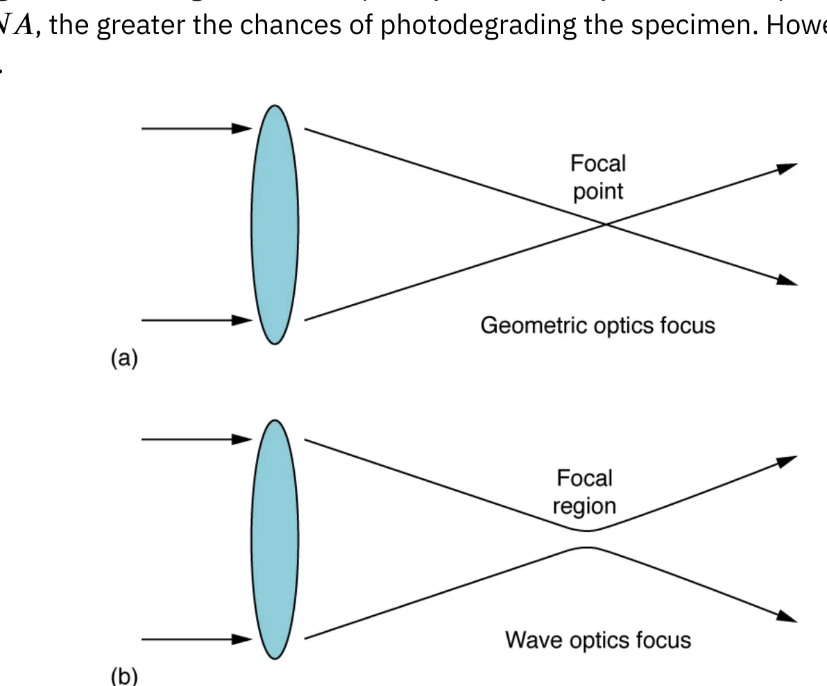
◀ Previous2 / 2
1Thin films and color2Thin films and color
Thin films and color
Thin films and color
The bright colors of an oil slick floating on water, or of a sunlit soap bubble, are caused by interference. The brightest colors are those that interfere constructively. This interference happens between light reflected from the two different surfaces of a thin film
so the effect is called thin film interference.
Interference is most noticeable when an object is about the size of a wavelength of light.
A thin film is one whose thickness is smaller than a few times the wavelength of light.
Color is linked to wavelength, and every interference effect depends on the ratio of the wavelength to the size of the object.
So a film with different thicknesses shows different colors at different places.
1 / 2Next ▶
Soap bubbles show bright, shifting colors when sunlight reflects from their very thin walls. Image: OpenStax, College Physics for AP Courses 2e, CC BY 4.0.
Thin films and color
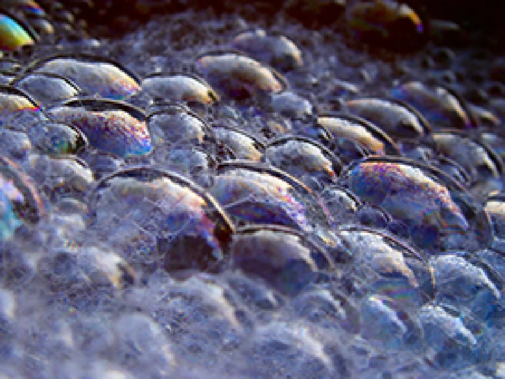 ⤢ Enlarge
Thin films and color
Early measurements of such films were made by Agnes Pockels, a self-taught German chemist who studied soapy and greasy films on water.
She built a trough for measuring surface films.
Lord Rayleigh supported her work and helped her results reach the journal Nature, even though social barriers kept women from publishing on their own.
Her trough became the basis for the modern version described later in this lesson.
◀ Previous2 / 2
Light reflects from the top and the bottom surfaces of a thin film, and the two reflected rays interfere with each other. Image: OpenStax, College Physics for AP Courses 2e, CC BY 4.0.
The two reflected rays
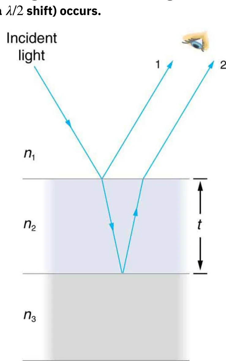 ⤢ Enlarge
The two reflected rays
Light striking a film is partly reflected from the top surface
this is ray 1. The rest enters the film. Part of it reflects from the bottom surface and emerges from the top as ray 2. Ray 2 can then interfere with ray 1. Because ray 2 travels farther through the film, the two rays can arrive in phase or out of phase.
1Phase change on reflection2Phase change on reflection
Phase change on reflection
1
A puzzle comes up for very thin films.
2
The extra path of ray 2 is almost zero
so why would a very thin soap film look dark rather than bright?
3
The answer is that light can change phase when it reflects.
4
The rule is this: when light reflects from a medium with a higher index of refraction than the medium it is traveling in, the reflected wave undergoes a half-cycle phase shift,
which is equal to a half-wavelength shift.
5
Reflection from a medium with a lower index produces no shift.
6
For a soap bubble
which is essentially water with air on both sides, ray 1 reflects from air into water and gets a half-wavelength shiftwhile ray 2 reflects from water into air and gets none.
1 / 2Next ▶
Phase change on reflection
Phase change on reflection
For a very thin bubble the two rays are therefore exactly out of phase, and destructive interference occurs at all visible wavelengths.
The bubble looks dark where it is thinnest, and it also looks dark at the point where it finally breaks.
◀ Previous2 / 2
1Path difference and film thickness2Path difference and film thickness
Path difference and film thickness
1
The second key factor is the thickness of the film compared with the wavelength of light.
2
For light arriving perpendicular to the surface, ray 2 travels an extra distance of about 2t
where t is the film thickness in m (or nm).
3
The wavelength inside the film is shorter than in vacuum: λn = λ / n.
4
Here λ is the vacuum wavelength in m, n is the index of refraction (no unit), and λn is the wavelength in the film in m.
5
Whether the film gives constructive or destructive interference depends on whether the path difference is a whole or half multiple of the wavelength in the film, and on whether a phase shift occurs. Using the path difference 2t, the conditions are:
1 / 2Next ▶
Path difference and film thickness
Path difference and film thickness
One phase shift (for example, a soap bubble in air): constructive when 2nt = (k + ½)λ, and destructive when 2nt = kλ.
No net phase shift,
or two equal shifts that cancel : constructive when 2nt = kλ,
(for example, a coating on glass with a higher index)
and destructive when 2nt = (k + ½)λ.
Here k = 0, 1, 2, … is a whole number with no unit, t and λ are in m, and n has no unit. For white light falling on a film whose thickness varies, each wavelength is reinforced at a different thickness
so you see rainbow colors.
◀ Previous2 / 2
Thin film technology
Thin film technology
Thin film interference became the foundation of a large field of research and industry in the 1920s and 1930s, at General Electric.
Irving Langmuir pioneered a method for producing ultra-thin layers on materials.
Katharine Burr Blodgett built on his work with a method for stacking and compressing these layers to make a film of a chosen thickness and quality.
The device they developed is the Langmuir-Blodgett trough.
It is based on the principles of Agnes Pockels and is still used in laboratories today.
The earliest widely applied result was non-reflective glass
which Blodgett patented in 1938. It was used almost at once in the film Gone With the Wind. Cameras, microscopes, telescopes and many other instruments still rely on this invention.
1Air wedge between microscope slides2Air wedge between microscope slides
Air wedge between microscope slides
1
When two very flat microscope slides touch at one edge and are separated slightly at the other, the wedge of air between them grows very uniformly.
2
A phase shift happens at the second glass surface but not at the first
so the line where the slides touch is dark.
3
White light produces repeating rainbow bands, going from violet to red again and again as the gap grows.
4
The bands become harder to see as the gap grows
because small changes in the angle of incidence have larger effects on the path difference.
5
With pure-wavelength light, the result is simple bright and dark bands instead of rainbow colors.
1 / 2Next ▶
Two glass slides form a wedge of air, and the colored bands are interference fringes produced by the changing gap. Image: OpenStax, College Physics for AP Courses 2e, CC BY 4.0.
Air wedge between microscope slides
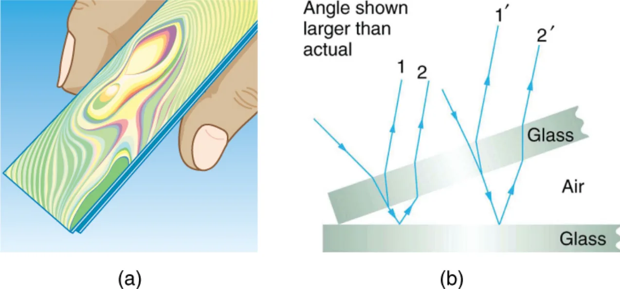
◀ Previous2 / 2
1Newton’s rings and precision optics2Newton’s rings and precision optics
Newton’s rings and precision optics
Newton’s rings and precision optics
Thin film interference is also used to make optical instruments.
A lens or mirror is compared with a master while it is being ground,
so its surface can be shaped to an accuracy of less than one wavelength over the whole surface.
When the flat surfaces of two lenses are pressed together, circular bands called Newton’s rings appear.
Isaac Newton described them in detail
but Robert Hooke discovered them, and Newton did not believe they were caused by the wave nature of light.
Each successive ring of a given color means that the path difference has changed by one wavelength. Because the path goes across the air gap and back, the gap itself changes by half a wavelength from one ring to the next. This makes the method very precise. If the lens surfaces were perfect, no rings would appear.
1 / 2Next ▶
Newton’s rings are circular interference fringes formed by a thin air gap between two nearly flat lens surfaces. Image: OpenStax, College Physics for AP Courses 2e, CC BY 4.0.
Newton’s rings and precision optics
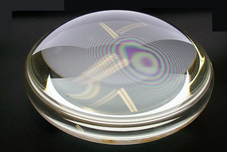
◀ Previous2 / 2
Iridescence in nature and industry
Iridescence in nature and industry
The wings of some moths and butterflies have nearly iridescent colors. Their color comes partly from pigment and partly from constructive interference of certain wavelengths reflected from a thin film coating on the wing surface. Car manufacturers also offer special paint finishes that use thin film interference to produce their colors.
A more expensive paint option relies on the path length difference between reflected rays changing with viewing angle
so the colors shift as the car is turned.
Security features on credit cards, banknotes, driving licenses and similar items that are prone to forgery use thin film interference, diffraction gratings,
or holograms.
Australia led the way with dollar bills printed on polymer, with a diffraction grating security feature that makes the currency difficult to forge.
Other countries, such as New Zealand and Taiwan, use similar technologies
while United States currency includes a thin film interference effect.
1Problem-solving strategies for wave optics2Problem-solving strategies for wave optics
Problem-solving strategies for wave optics
1
Step 1. Examine the situation to determine whether interference is involved. Identify whether slits or thin film interference are considered in the problem.
2
Step 2. If slits are involved, note that diffraction gratings and double slits produce very similar interference patterns
but gratings have narrower (sharper) maxima. A single-slit pattern has a large central maximum and smaller maxima to the sides.
3
Step 3. If thin film interference is involved, take note of the path length difference between the two rays that interfere. Use the wavelength in the medium involved
because it differs from the wavelength in vacuum. Also remember that there is an additional half-wavelength phase shift when light reflects from a medium with a greater index of refraction.
4
Step 4. Identify exactly what must be determined (the unknowns). A written list is useful, and so is a labeled diagram of the situation.
5
Step 5. List what is given or can be inferred from the problem (the knowns).
6
Step 6. Solve the appropriate equation for the unknown and enter the knowns. Slits, gratings and the Rayleigh limit all involve equations.
1 / 2Next ▶
Problem-solving strategies for wave optics
1
Step 7. For thin film interference, constructive interference occurs for a total phase shift that is a whole number of wavelengths, and destructive interference occurs for a total shift that is a half-integral number of wavelengths. Always remember that crest to crest is constructive, whereas crest to trough is destructive.
2
Step 8. Check whether the answer is reasonable. Angles in interference patterns cannot be greater than 90°, for example.
◀ Previous2 / 2
1Example 27.6: Thinnest non-reflective coating on a lens2Example 27.6: Thinnest non-reflective coating on a lens3Example 27.7: Thicknesses of a soap bubble for red light4Example 27.7: Thicknesses of a soap bubble for red light
Example 27.6: Thinnest non-reflective coating on a lens
1
Problem: A camera lens is coated with a thin layer of magnesium fluoride (n = 1.38) to reduce reflection of 550 nm light. The glass has n = 1.52, and air has n = 1.00. What is the thinnest coating that gives destructive interference?
2
Strategy: Ray 1 reflects from air into the film
which has a higher indexso it has a half-wavelength shift.
3
Ray 2 reflects from the film into the glass
which also has a higher indexso it has a half-wavelength shift too.
4
The two shifts cancel.
5
Destructive interference then needs 2nt = (k + ½)λ, and the thinnest film has k = 0
so 2nt = λ / 2.
6
Solution: t = λ / (4n) = 550 nm / (4 × 1.38) = 550 nm / 5.52 ≈ 99.6 nm. As a check, the wavelength in the film is 550 / 1.38 ≈ 398.6 nm, and one quarter of that is 99.6 nm.
1 / 4Next ▶
Example 27.6: Thinnest non-reflective coating on a lens
Example 27.6: Thinnest non-reflective coating on a lens
Discussion: The thinnest layer gives destructive interference over a broader range of incident angles
so the light is reduced over more angles. Other wavelengths are only partly cancelledso these are called non-reflective coatingswhich is only an approximate description. Such coatings are used on car windows and sunglasses.
◀ Previous2 / 4Next ▶
Example 27.7: Thicknesses of a soap bubble for red light
1
Problem: A soap film, with the same index as water (n = 1.33), in air is lit by red light of wavelength 650 nm. (a) What are the three smallest thicknesses that give constructive interference? (b) What are the three smallest thicknesses that give destructive interference?
2
Strategy: Ray 1 has a half-wavelength shift at the top surface, and ray 2 has none.
3
There is therefore one phase shift.
4
Constructive interference needs 2nt = (k + ½)λ, and destructive interference needs 2nt = kλ.
5
Both can be written as t = (a number) × λ / (2n).
6
Here λ / (2n) = 650 nm / (2 × 1.33) = 650 nm / 2.66 ≈ 244.4 nm.
◀ Previous3 / 4Next ▶
Example 27.7: Thicknesses of a soap bubble for red light
Example 27.7: Thicknesses of a soap bubble for red light
Solution (a): For constructive interference, t = (k + ½) × 244.4 nm. For k = 0, t = 0.5 × 244.4 ≈ 122 nm. For k = 1, t = 1.5 × 244.4 ≈ 367 nm. For k = 2, t = 2.5 × 244.4 ≈ 611 nm.
Solution (b): For destructive interference, t = k × 244.4 nm. For k = 0, t = 0 nm
the film is dark even at zero thickness because of the phase shift at the top surface. For k = 1, t = 244 nm. For k = 2, t = 2 × 244.4 ≈ 489 nm.
Discussion: If the bubble is lit by pure red light, the bands run dark at 0 nm, bright at about 122 nm, dark at about 244 nm, bright at about 367 nm, dark at about 489 nm, and bright at about 611 nm. If the bubble changes smoothly in thickness, like a wedge, these bands are evenly spaced.
◀ Previous4 / 4
Key terms
| Term | Meaning |
|---|---|
| Thin film interference | Interference between light reflected from the two surfaces of a film that is only a few wavelengths thick or less. |
| Thin film | A layer whose thickness is smaller than a few times the wavelength of light. |
| Interference | The combination of two or more waves, which adds or cancels their effects depending on their phase. |
| Constructive interference | Interference in which waves are in phase, so they reinforce each other and the result is brighter. |
| Destructive interference | Interference in which waves are out of phase, so they cancel each other and the result is darker. |
| Phase shift (phase change) on reflection | A half-cycle change in a reflected wave, which occurs when it reflects from a medium with a higher index of refraction. |
| Index of refraction | The ratio of the speed of light in vacuum to its speed in a material; it has no unit. |
| Path length difference | The extra distance one ray travels compared with another, measured in m. |
| Wavelength in a medium | The wavelength of light inside a material, equal to the vacuum wavelength divided by n, in m. |
| Non-reflective coating | A thin film, usually a fraction of a micrometer thick, that reduces reflection through destructive interference. |
| Langmuir-Blodgett trough | A device for depositing ultra-thin layers in a precise, controlled thickness. |
| Newton’s rings | Circular interference fringes formed by a thin air gap between two nearly flat lens surfaces. |
| Focal spot | The small region of finite size where wave optics says light is focused, instead of a true point. |
| Iridescence | Color that changes with the viewing angle, often caused by thin film interference. |
1Avoid these mistakes2Avoid these mistakes3Avoid these mistakes
Avoid these mistakes
1Avoid this
Forgetting the phase shift at reflection: a shift occurs only when light reflects from a medium with a higher index,Avoid this
and the answer changes depending on whether there is one shift or zero or two.Avoid this
2Avoid this
Using the vacuum wavelength in the thickness formula. Inside the film the wavelength is λ / n, so the film wavelength must be used.Avoid this
3Avoid this
1 / 3Next ▶
Avoid these mistakes
Treating the extra path as t instead of 2t. For light at normal incidence, ray 2 travels through the film twice.Avoid this
4Avoid this
Swapping the constructive and destructive conditions when there is one phase shift, which is the case for a soap bubble in air.Avoid this
5Avoid this
Forgetting that a very thin soap film is dark because of the phase shift, and so it is also dark at zero thickness.Avoid this
6Avoid this
◀ Previous2 / 3Next ▶
Avoid these mistakes
Saying that each Newton’s ring means the air gap changes by one wavelength.Avoid this
The path difference changes by one wavelength, so the gap changes by half a wavelength.Avoid this
◀ Previous3 / 3