Curriculum
OCR A Level Physics A H556
1. Development of Practical Skills in Physics
0/56
-
1. Development of Practical Skills in Physics
 Preview
-
1.1.1 Experimental Design
Preview
-
1.1.1 Experimental Design - Check yourself
 Preview
-
1.1.2 Control Variables
Preview
-
1.1.2 Control Variables - Check yourself
Preview
-
1.1.3 Refining of Experimental Design
Preview
-
1.1.3 Refining of Experimental Design - Check yourself
Preview
-
1.1.4 Investigative Approaches and Methods
Preview
-
1.1.4 Investigative Approaches and Methods - Check yourself
Preview
-
1.1.5 Using Practical Equipment and Materials
Preview
-
1.1.5 Using Practical Equipment and Materials - Check yourself
Preview
-
1.1.6 Appropriate Units for Measurements
Preview
-
1.1.6 Appropriate Units for Measurements - Check yourself
Preview
-
1.2.1 Presenting and Interpreting Results
Preview
-
1.2.1 Presenting and Interpreting Results - Check yourself
Preview
-
1.2.2 Analysing Quantitative Data
Preview
-
1.2.2 Analysing Quantitative Data - Check yourself
Preview
-
1.2.3 Plotting and Interpreting Graphs
Preview
-
1.2.3 Plotting and Interpreting Graphs - Check yourself
Preview
-
1.2.4 Evaluating Results and Drawing Conclusions
Preview
-
1.2.4 Evaluating Results and Drawing Conclusions - Check yourself
Preview
-
1.2.5 Observations and Measurements
Preview
-
1.2.5 Observations and Measurements - Check yourself
Preview
-
1.2.6 Presenting in a Scientific Way
Preview
-
1.2.6 Presenting in a Scientific Way - Check yourself
Preview
-
1.2.7 Use of Software and Tools
Preview
-
1.2.7 Use of Software and Tools - Check yourself
Preview
-
1.2.8 Research and Citation Skills
Preview
-
1.2.8 Research and Citation Skills - Check yourself
Preview
-
1.2.9 Precision, Accuracy and Experimental Limitations
Preview
-
1.2.9 Precision, Accuracy and Experimental Limitations - Check yourself
Preview
-
1.2.11 Methods to Increase Accuracy
Preview
-
1.2.11 Methods to Increase Accuracy - Check yourself
Preview
-
1.3.1 Using Appropriate Instruments and Techniques
Preview
-
1.3.1 Using Appropriate Instruments and Techniques - Check yourself
Preview
-
1.3.2 Analogue Apparatus and Interpolation
Preview
-
1.3.2 Analogue Apparatus and Interpolation - Check yourself
Preview
-
1.3.3 Use of Digital Instruments
Preview
-
1.3.3 Use of Digital Instruments - Check yourself
Preview
-
1.3.4 Stopwatch and Light Gates
Preview
-
1.3.4 Stopwatch and Light Gates - Check yourself
Preview
-
1.3.5 Calipers, Micrometers and Vernier Scales
Preview
-
1.3.5 Calipers, Micrometers and Vernier Scales - Check yourself
Preview
-
1.3.6 Circuits
Preview
-
1.3.6 Circuits - Check yourself
Preview
-
1.3.7 Signal Generators and Oscilloscope
Preview
-
1.3.7 Signal Generators and Oscilloscope - Check yourself
Preview
-
1.3.8 Using a Laser or Light Source
Preview
-
1.3.8 Using a Laser or Light Source - Check yourself
Preview
-
1.3.9 Computer Modelling and Data Logger
Preview
-
1.3.9 Computer Modelling and Data Logger - Check yourself
Preview
-
1.3.10 Ionising Radiation and Detectors
Preview
-
1.3.10 Ionising Radiation and Detectors - Check yourself
Preview
-
3.2.3 Significant Figures
Preview
-
3.2.3 Significant Figures - Check yourself
Preview
-
1.2.10 Significant Figures
Preview
2. Foundations in Physics
0/29
3. Forces and Motion
0/108
4. Electrons, Waves and Photons
0/71
OCR H556 chapter questions and answers
0/2
Text lesson
1.3.6 Circuits
1.3.6 Circuits — OCR A Level Physics A notes: Construct and use practical circuits with ammeters, voltmeters, variable resistors and potential dividers, and take safe, accurate electrical measurements.
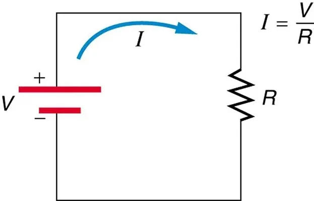
Circuit schematics and standard symbols: Schematic of a battery connected across a resistor, with current leaving the positive terminal.
Circuit components and symbols
 ⤢ Enlarge
Circuit components and symbols
A practical circuit is built from a power supply (cell, battery or low-voltage supply), connecting leads, a switch, the component under test and meters. The standard symbols are used in diagrams: a cell, a resistor (rectangle), a variable resistor (rectangle with an arrow), a filament lamp, a diode, a thermistor, a light-dependent resistor, and the meters shown as a circle containing A or V.
Build the main series loop first, from the positive terminal through each component back to the negative terminal. Add the voltmeter last, in parallel across the component being measured. Keep the switch open until the circuit has been checked, and close it only while taking a reading, since prolonged current heats components and changes their resistance.
1Ammeter2Voltmeter3Voltmeter
Ammeter
1
An
2
ammeter
3
is connected in
4
series
5
with the component
so the same current flows through it. An ideal ammeter has zero resistanceso it does not alter the current. Real ammeters have a small resistance.
1 / 3Next ▶
Voltmeter
Voltmeter
A
voltmeter
parallel
with the component
so that it measures the potential difference between the two ends. An ideal voltmeter has infinite resistance and draws no current. Real voltmeters have large resistance (digital: 10 MΩ typical).
Observe the polarity: the meter terminal marked + (red) goes towards the positive side of the supply. Select a sensible range, starting with the highest range if the size is unknown and switching down for greater resolution. Check for zero error before connecting, especially on analogue meters.
◀ Previous2 / 3Next ▶

1Varying the current: rheostat and potential divider2Varying the current: rheostat and potential divider
1Typical experiments2Typical experiments
1Safety and accuracy2Safety and accuracy
1Worked examples2Worked examples3Worked examples4Worked examples
Key terms
| Term | Meaning |
|---|---|
| Ammeter | Meter connected in series that measures current. |
| Voltmeter | Meter connected in parallel that measures potential difference. |
| Rheostat | Variable resistor used in series to change current. |
| Potential divider | Arrangement giving an adjustable fraction of the supply voltage. |
| I–V characteristic | Graph of current against potential difference for a component. |
| Terminal pd | Potential difference across the terminals of a cell when a current flows. |
1Avoid these mistakes2Avoid these mistakes