Curriculum
AP PHYSICS 2
9. Thermodynamics
0/52
10. Electric Force, Field, and Potential
0/6211. Electric Circuits
0/6811.3.1Resistance as opposition to charge flow11.3.2Resistivity and the geometry of a conductor11.3.3Resistivity and temperature11.3.4Ohm’s law and ohmic materials11.3.5Finding resistance from an I–V graph11.3.6Resistors and thermal energy11.3.7Worked examples11.3.8Key terms11.3.9Avoid these mistakes
11.5.1Series and parallel connections11.5.2Equivalent resistance of resistors in series11.5.3Equivalent resistance of resistors in parallel11.5.4Analysing a combined circuit11.5.5Real batteries and internal resistance11.5.6Ideal and nonideal ammeters and voltmeters11.5.7Worked examples11.5.8Key terms11.5.9Avoid these mistakes
12. Magnetism and Electromagnetism
0/3813. Geometric Optics
0/4214. Waves, Sound, and Physical Optics
0/751.1Describing any wave1.2Transverse and longitudinal waves, and electromagnetic waves1.3Boundaries, intensity and motion of sources1.4Superposition, beats and standing waves1.5Diffraction and interference of light1.6How the topics connect1.7Key equations of Unit 141.8Key terms1.9Avoid these mistakes
14.1.1Waves transfer energy, not matter14.1.2Wave pulses and continuous periodic waves14.1.3Mechanical and electromagnetic waves and the medium14.1.4Speed of waves on a string and in a medium14.1.5Transverse and longitudinal waves14.1.6Amplitude, loudness and energy14.1.7Worked examples14.1.8Key terms14.1.9Avoid these mistakes
15. Modern Physics
0/65
Text lesson
11.6 Kirchhoff’s Loop Rule
Kirchhoff’s Loop Rule
11.6 Energy changes around a circuit loop
Energy changes around a circuit loop
- In a simple electric circuit, charges gain energy when they pass through a battery and lose energy when they pass through resistors and other elements.
- The energy changes can be described in terms of charges moving through electric potential differences within the circuit elements.
- A charge that moves through a battery from its negative terminal to its positive terminal gains electric potential energy, and a charge that moves through a resistor in the direction of the current loses electric potential energy as it does work against the resistance.
- The potential difference across an element is the change in electric potential energy per unit charge for a charge moving through it, and it is measured in volts (V).
Loop energy
- Because electric potential energy is a conserved quantity in an electric field, the total change in potential around any closed path returns to zero.
- This is the basis of Kirchhoff’s loop rule.
11.6 Kirchhoff’s Loop Rule · 1 / 7
11.6 Kirchhoff’s loop rule
Kirchhoff’s loop rule
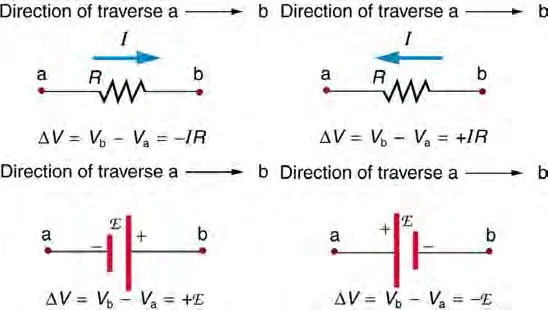
- Kirchhoff’s loop rule states that the sum of the potential differences across all circuit elements in a single closed loop must equal zero: Σ ΔV = 0.
- Here each ΔV is in volts (V), and the sum is taken around the loop in one direction.
- The rule is a consequence of the conservation of energy, because a charge that returns to its starting point has the same electric potential energy it started with.
- To apply the rule, choose a direction to travel around the loop and keep to it.
- A battery contributes +ε when it is traversed from its negative terminal to its positive terminal, and −ε when it is traversed from positive to negative.
- A resistor contributes −IR when the loop is traversed in the same direction as the current, because the potential falls along the direction of current.
- If the loop is traversed against the current, the resistor contributes +IR.
- Here I is the current in amperes (A) and R is the resistance in ohms (Ω).
- The sign convention for batteries and resistors must be applied consistently.
- If the loop is traversed clockwise and the current is assumed to be clockwise, the equation for a loop containing one battery of emf ε and two resistors R1 and R2 is ε − IR1 − IR2 = 0.
- If the calculated current is negative, the current actually flows in the opposite direction to the one assumed.
11.6 Kirchhoff’s Loop Rule · 2 / 7
11.6 Using the loop rule with several batteries
Using the loop rule with several batteries
- A loop may contain more than one battery.
- Batteries whose emfs drive current in the same direction add together, and batteries whose emfs oppose each other subtract.
- The net emf of the loop is the sum of the emfs with their signs fixed by the direction of traversal.
- Ideal batteries of equal and opposite emf in a single loop produce no net driving emf, so no current flows around that loop.
Several batteries
- A loop with a real battery must include the internal resistance r of the battery as an additional resistance in the loop.
- The battery then contributes +ε − Ir when traversed from its negative terminal to its positive terminal, and this is the same as the terminal potential difference relation ΔVterminal = ε − Ir.
11.6 Kirchhoff’s Loop Rule · 3 / 7
11.6 Electric potential as a function of position in a loop
Electric potential as a function of position in a loop
- The values of electric potential at points in a circuit can be shown on a graph of electric potential against position around a loop.
- Choose one point in the loop as the reference point and set its potential to zero, which is often called ground.
- Travel around the loop, and at each element draw the potential change: the potential rises by ε across an ideal battery from negative to positive terminal, and falls by IR across each resistor in the direction of current.
- The graph is a sequence of steps and slopes.
- A resistor appears as a sloped line falling in the direction of current, and an ideal battery appears as a vertical jump upward.
- Because the loop rule holds, the graph returns to its starting value after one complete circuit of the loop.
- The vertical height of the drop across any resistor is the potential difference across it, and the total height of all the drops equals the total rise from the batteries.
- A wire of negligible resistance has no change in potential along its length, so it appears on the graph as a horizontal line.
- Potentials are relative, so the choice of the zero reference point changes the values on the graph but not the potential differences between points.
11.6 Kirchhoff’s Loop Rule · 4 / 7
11.6 Worked examples
Worked examples
- Example 1 · Single loop with two resistors
- Question
- An ideal 12 V battery is connected in series with a 4.0 Ω resistor and an 8.0 Ω resistor to form a single loop.
- Find the current in the loop and the potential difference across the 8.0 Ω resistor.
- Sketch the electric potential around the loop starting from the negative terminal of the battery at 0 V.
- Traverse the loop in the direction of the current.
- The loop rule gives ε − IR1 − IR2 = 0, so I = ε/(R1 + R2) = 12 V/12.0 Ω = 1.0 A.
- The potential difference across the 8.0 Ω resistor is ΔV = IR2 = (1.0 A)(8.0 Ω) = 8.0 V.
- The 4.0 Ω resistor has a drop of 4.0 V.
- Starting at 0 V, the potential rises to 12 V across the battery, falls by 4.0 V to 8.0 V across the 4.0 Ω resistor, and falls by 8.0 V back to 0 V across the 8.0 Ω resistor.
- Answer
- The current is 1.0 A and the potential difference across the 8.0 Ω resistor is 8.0 V.
- The potential graph is a jump up of 12 V, then a drop of 4.0 V and a drop of 8.0 V, which returns to 0 V.
- Question
- A loop contains an ideal 12 V battery and an ideal 6.0 V battery connected with their positive terminals facing in opposite directions, and a total resistance of 3.0 Ω.
- Find the current in the loop and its direction, taking the direction of the 12 V battery’s driving emf as clockwise.
- Traverse the loop clockwise.
- The 12 V battery is traversed from its negative to its positive terminal, so it contributes +12 V.
- The 6.0 V battery opposes this, so it contributes −6.0 V.
- The resistors contribute −I(3.0 Ω) for a current assumed clockwise.
- The loop rule gives 12 V − 6.0 V − (I)(3.0 Ω) = 0, so I = 6.0 V/3.0 Ω = 2.0 A.
- The result is positive, so the current flows clockwise.
- Answer
- The current is 2.0 A, flowing clockwise, in the direction of the stronger 12 V battery.
- Example 3 · Loop with a real battery
- Question
- A battery of emf 6.0 V and internal resistance 1.0 Ω is connected in a single loop with resistors of 2.0 Ω and 3.0 Ω in series.
- Assume the wires are ideal.
- Find the current in the loop and the potential difference across the 2.0 Ω resistor.
- The internal resistance is in series with the external resistors, so the total resistance is 1.0 Ω + 2.0 Ω + 3.0 Ω = 6.0 Ω.
- The loop rule gives ε − I(r + R1 + R2) = 0, so I = 6.0 V/6.0 Ω = 1.0 A.
- The potential difference across the 2.0 Ω resistor is (1.0 A)(2.0 Ω) = 2.0 V.
- The terminal potential difference across the battery is 6.0 V − (1.0 A)(1.0 Ω) = 5.0 V, which equals the total drop across the two external resistors, 2.0 V + 3.0 V = 5.0 V.
Answer
- The current is 1.0 A and the potential difference across the 2.0 Ω resistor is 2.0 V.
- The check confirms that the loop sums to zero.
11.6 Kirchhoff’s Loop Rule · 5 / 7
11.6 Key terms
Key terms
11.6 Kirchhoff’s Loop Rule · 6 / 7
11.6 Avoid these mistakes
Avoid these mistakes
- Changing the traversal direction partway around a loop.
- The sign of each term depends on the direction chosen, so one direction must be kept for the whole loop.
- Giving a resistor a positive sign when the loop is traversed along the current.
- The potential falls across a resistor in the direction of current, so the term is −IR.
- Adding the emfs of two batteries whose positive terminals face in opposite directions
- Opposing emfs subtract in a loop.
- Reading a negative answer for the current as an error.
- A negative current means that the current flows opposite to the direction that was assumed.
- Drawing the potential graph with the wrong sign for a battery.
- A battery raises the potential when a charge passes from its negative terminal to its positive terminal.
Avoid→Forgetting the internal resistance of a real battery in the loop equation, which makes the current too large.
11.6 Kirchhoff’s Loop Rule · 7 / 7
Well done! You finished this lesson
What would you like to do next?